diy solar

diy solar

Solar panels to bus bars

Aldricoak

New Member
Joined
Jan 7, 2022
Messages
53
I have two arrays. Each array has six panels. The panels are wired as 2S3P on each array. Currently I have each array connected to it's own Epever Tracer 4210an. Each MPPT feedings it's own battery bank. Bank #1 is 24v Flooded 660amp. Bank#2 24v Lifepo4 400amp.
Is it possible to tie in all arrays into a positive and negative bus bar group and then connect the mppt's to the bus bars to feed the charge controllers?
 
Your last sentence is a little confusing, since the mppt's and the charge controllers are the same thing... But I think what you're asking is: "Can I connect two currently separate 2S3P arrays in a single 2S6P array and hook up two charge controllers to that single array?"
And the short answer is: "No."
Multiple charge controllers on the same array will fight each other. Have a look at section 2.1 of your user manual, it says "Multiple same models of controllers can be installed in parallel on the same battery bank to achieve higher charging current. Each controller must have its own solar module(s)."
 
I will need to draw it out and include the pic. I am driving at the moment. Will include the drawing in my next post.
 
I have two arrays. Each array has six panels. The panels are wired as 2S3P on each array. Currently I have each array connected to it's own Epever Tracer 4210an. Each MPPT feedings it's own battery bank. Bank #1 is 24v Flooded 660amp. Bank#2 24v Lifepo4 400amp.
Is it possible to tie in all arrays into a positive and negative bus bar group and then connect the mppt's to the bus bars to feed the charge controllers?
No
Two MPPT's connected to the same panels will fight for control over the MPP. And neither will find a good production level.
 
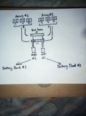
IMG_20230327_175555.jpg
This is what I am looking to combine. Purpose is to maximize solar energy during cloudy days when one battery bank requires charging over another.
 
Please explain, so I can learn.
By connecting your two arrays together at the bus bar, they're no longer two separate arrays. Like I said above, you would now have a single 2S6P array. You can't connect two MPPTs to that one array and expect them both to work.
I don't have a perfect, 100% grasp of exactly how this works, but this if my best interpretation:
MPPTs find the MPP by (this is simplified) varying input current and measuring if the power received goes up or down, then varying again based on that result. So even if they did both happen to find a voltage-current point where both worked well, one or both of them would deviate from that immediately, and thus give weird/bad feedback to the other MPPT. So like we said, they fight each other and neither works great.
 
Your MPPTs have to correctly read a battery bank's info to correctly charge them.
If you have two MPPTs trying to charge two battery banks the info will get confused and the MPPTs will not know how to charge the banks correctly.
You would be better off to parallel the battery banks to a busbar, then parallel the individual MPPTs to the busbar.
That way the battery banks are giving a combined set of info and the MPPTs are reading the overall combined battery bank.
Each MPPT will then provide charging without having to fight each other.
I use 2xMPPTs (Victron 150/70) each MPPT handles their own array(s), and each is connected to my busbar. Then my batteries are also parrallel connected to the busbar (albeit a Class-T in between).
I wouldn’t parallel a flooded battery bank with a LFP bank.
 
Essentially I was simply looking to combine the power of two arrays on low light collection days by means of bus bars. The charge controllers are post bus bars and still feed their own respective battery banks. During low light days, one of the charge controllers would be switched off while other remains on collecting the most of the combined arrays. This was my rational of thinking.
 
That could probably be accomplished with some smartly placed solar disconnects, but you'd need to make sure that your system would be safe if you happened to have all panels connected to one MPPT on a sunny day. Even if you wouldn’t plan to do that on purpose, you don’t want an unexpected hole in the clouds to fry an MPPT. You would have to make sure your 12 panels don’t exceed the maximum input power for your MPPT (check the manual), and if they aren’t already, you would need to fuse each series string.
In the end it may not be worth it.
 
Essentially I was simply looking to combine the power of two arrays on low light collection days by means of bus bars. The charge controllers are post bus bars and still feed their own respective battery banks. During low light days, one of the charge controllers would be switched off while other remains on collecting the most of the combined arrays. This was my rational of thinking.
This is fine, as long as both aren't on at the same time. Overpaneling is fine on amperage. But VOC is a hard number. (Never exceed VOC)
 
That could probably be accomplished with some smartly placed solar disconnects, but you'd need to make sure that your system would be safe if you happened to have all panels connected to one MPPT on a sunny day. Even if you wouldn’t plan to do that on purpose, you don’t want an unexpected hole in the clouds to fry an MPPT. You would have to make sure your 12 panels don’t exceed the maximum input power for your MPPT (check the manual), and if they aren’t already, you would need to fuse each series string.
In the end it may not be worth it.
I do have disconnects and forty amp fuses in place as protection for the mppt's. While I didn't include the safety features on my rough drawing they (disconnects and fuses) would be in place post bus bars, but before the mppt's. I have disconnects and fuses on each array as well.
 
I should mention, I did take into account VOC, amperes, volts on wire gauge size and fusing limitations. Electrically (by means of flowing energy per parameter limitations of all components) it appears to work. I also thought of including a four way switch with relays to automate the whole process via monitoring devices which have relay switch actuators- i. e. Junctek KG series battery monitors.
 
Bank #1 is 24v Flooded 660amp. Bank#2 24v Lifepo4 400amp.

Another possible path for you is to use a battery to battery charger to move power from one bank to the other.

Beat me to it.

Consider charging lead-acid battery off lithium battery. Lead-acid should be fully recharged and floated. Lithium is better for many cycles. Your inverter could run off the lead-acid, and a DC/DC charge controller keep it charged from lithium.

I plan to do that (eventually) for my pickup, which will have 12V MSW inverter to run tools. Once I add a lithium battery I would cascade like this.

I also want to do it for my home system with 48V AGM bank.
 
Back
Top