diy solar

diy solar

solark tech made remote setting changes and batteries no longer working for peak coverage on solark 15k

Subestile

New Member
Joined
May 17, 2022
Messages
65
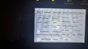
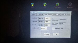
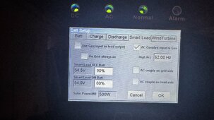
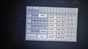
Solark changed my settings to fix the issue with my batteries not powering the house in a grid down situation (allegedly have not been able to test this actually fixed it) but now the solark sees zero house power draw and wont use batteries at all for peak power load management. the settings the changed were removing CTs (per solark tech support) and changing from limited power to home to limited power to limited power to load. my system is 19 kw of PV to the solark DC and 7.4kw ac coupled. I do not use the load connections only the grid. I am guessing the CS rep at solark either completely misunderstood how my system is installed or something got unchecked when they remotely redid the settings. I tried reverting the changes and when I hooked up the CTs they gave a reading of -29kw back to grid so it was obviously not working correctly. it cost me over $50 in peak charges yesterday due to this situation and need to resolve asap. any sugestions would be appreciated before I reset everything and recommission the solark tonight to attempt to get the CTs to read correctly like they were prior to the solark tech making remote changes.

I have a single breaker panel (solar ready Siemens 200a main panel) CTs were functioning correctly prior to the change.

*moved from general my apologies
 
1717950048171.png
Do you have a diagram from your install? Can you post screenshots of your settings pages on the solark?

Page 20 of this document might be helpful. https://www.sol-ark.com/wp-content/uploads/15K-2P_Manual.pdf
will upload settings from mobile in a moment I took pictures last night incase I had to factory reset. decided to try and call solark again this morning on the way to work but had to leave another message that unfortunately I am not hopeful they will call back again today.
 

Attachments

  • IMG_1047.jpeg
    IMG_1047.jpeg
    272.5 KB · Views: 6
  • IMG_1048.jpeg
    IMG_1048.jpeg
    309.5 KB · Views: 6
  • IMG_1049.jpeg
    IMG_1049.jpeg
    319.7 KB · Views: 6
  • IMG_1050.jpeg
    IMG_1050.jpeg
    322.7 KB · Views: 6
  • IMG_1051.jpeg
    IMG_1051.jpeg
    294.9 KB · Views: 6
  • IMG_1052.jpeg
    IMG_1052.jpeg
    403.6 KB · Views: 6
  • IMG_1053.jpeg
    IMG_1053.jpeg
    365.7 KB · Views: 6
  • IMG_1054.jpeg
    IMG_1054.jpeg
    380.6 KB · Views: 6
  • IMG_1055.jpeg
    IMG_1055.jpeg
    445.9 KB · Views: 5
  • IMG_1057.jpeg
    IMG_1057.jpeg
    355.9 KB · Views: 5
  • IMG_1059.jpeg
    IMG_1059.jpeg
    356.3 KB · Views: 5
  • IMG_1060.jpeg
    IMG_1060.jpeg
    350.6 KB · Views: 5
  • IMG_1061.jpeg
    IMG_1061.jpeg
    327.4 KB · Views: 6
no only as shown in the diagram, the main panel is all I have, goes from grid into main breaker, solark goes into the solar breaker on the siemens solar ready 200am panel

1717954114518.png
Do you have a critical loads panel?
 
no only as shown in the diagram, the main panel is all I have, goes from grid into main breaker, solark goes into the solar breaker on the siemens solar ready 200am panel
Then you can't (safely) have power when the grid is down. You need something to physically disconnect your house from the grid. You inverter has that built in, but the disconnect is inside the inverter and it would keep the critical loads panel going when the grid is down.

To test, you can simulate a power outage by flipping your main breaker off.
 
Tech support obviously didn't understand your setup. In a grid down situation, the Sol-Ark disconnects the grid terminals and only powers the load terminals.
 
Tech support obviously didn't understand your setup. In a grid down situation, the Sol-Ark disconnects the grid terminals and only powers the load terminals.
this is my assumption as well

Then you can't (safely) have power when the grid is down. You need something to physically disconnect your house from the grid. You inverter has that built in, but the disconnect is inside the inverter and it would keep the critical loads panel going when the grid is down.

To test, you can simulate a power outage by flipping your main breaker off.
so to do what I am desiring leaving the grid lines connected to the solar breaker on the solark for back feeding and use battery backup in a grid down situation I would need to move everything to a subpanel that is powered by the load on the solark thus allowing the the battery to power that subpanel when the grid is down, in which case I should not just move the power from the Grid terminals to the load terminals on the solark as that could potentially backfeed to the grid when the grid is down and cause a dangerous situation for anyone working on the grid correct?
 
1717956613591.png
Then you can't (safely) have power when the grid is down. You need something to physically disconnect your house from the grid. You inverter has that built in, but the disconnect is inside the inverter and it would keep the critical loads panel going when the grid is down.

To test, you can simulate a power outage by flipping your main breaker off.
something such as this? I am obviously not an electrician by trade and continue to learn as this project unfolds.
 
I think I see another problem with your setup. The largest breaker you can put in a 200 A panel for solar backfeed is 40A. What size is your breaker?
 
I think I see another problem with your setup. The largest breaker you can put in a 200 A panel for solar backfeed is 40A. What size is your breaker?
this is a solar ready panel so that is not correct, it has its own 100a busbar for the solar. prior to solark changing my settings the backfeeding was functioning just fine as currently setup. 80a breaker currently installed by the electrician that did the final wiring setup. I think this is slightly pushing the 125% rule but its working just fine due to the locations of my panels and 3/4 facing east (52) and 1/4 facing west (20 panels)
 
so to do what I am desiring leaving the grid lines connected to the solar breaker on the solark for back feeding and use battery backup in a grid down situation I would need to move everything to a subpanel that is powered by the load on the solark thus allowing the the battery to power that subpanel when the grid is down, in which case I should not just move the power from the Grid terminals to the load terminals on the solark as that could potentially backfeed to the grid when the grid is down and cause a dangerous situation for anyone working on the grid correct?
That's correct.

Maybe it would be possible to connect the load side to your main panel if you can install a backfeeding breaker interlocked with the main breaker. But I don't know if it's code legal or Sol ark endorsed.

That would be a manual transfer process in the event of an outage.
 
That's correct.

Maybe it would be possible to connect the load side to your main panel if you can install a backfeeding breaker interlocked with the main breaker. But I don't know if it's code legal or Sol ark endorsed.

That would be a manual transfer process in the event of an outage.

it isn't legal as far as I know.

If you have it setup with batteries and solar panels the max output is 62.5amps. Which will run most of a common house unless you have high draw items like a hottub, pool heater, double oven, etc. If you have those things then they go into a main panel and you have the common stuff in the critical load panel.

If you have export configured it will backfeed the grid up to that 50 amps (no battery usage) if your solar can support it.

The other configuration is to have the grid lugs tied to a 70 or 80 amp breaker and nothing on the load lugs. Then it will always supply either 50 amps or 62.5 back to the "grid" and your in home stuff will consume what it wants and the rest goes back to the grid. The downside of this is you need an automatic transfer switch to disconnect the grid when power is lost, or you can use the CT clamps to detect that and all power will go out until the grid comes back.

In your diagram the "main panel" becomes a feed-through box which has slots for up to 4 inverted. And between the grid and your feed-through panel there is a main disconnect which is nothing but a box with a main breaker in it.


Look in the EG4 18kpv panel install guide on pages 31-38 for diagrams of the different ways to do it. The one on pages 33, 34 or 35 are the most common. You just substitute the Sol-Ark for the Eg4.

 
Thank you for all the info, I will reset the solark and reconfigure how it was before solark made the changes. I will have to redesign to do what I want it to do and have the grid down capabilities that I want while still allowing the backfeed desired. ideally I will care less about the back feeding once I increase the battery capacity to be able to cover more of the load overnight during the summer as it is better to use the power I generate as srp does not reimburse for grid sell nearly as much as they charge for even off peak power.
 
I think your issue from your diagram is you have your solark wired after your main breaker panel. The main advantage of the solark 15k is it has a 200amp bypass. So for most USA houses that have 200amp electrical service, it can be connected in between your electrical meter and your main breaker panel and you don't need to have a critical loads sub panel.

See my diagram for how mine is installed. My batteries can power any load at my house when the grid is down. My battery bank isn't that large so I'm somewhat limited and I do conserve when the grid is down. But 99% of the time it works without any issue.

Side note, the solark in this configuration also sees all power input, used, or output.

install_diagram.JPG
 
I think your issue from your diagram is you have your solark wired after your main breaker panel. The main advantage of the solark 15k is it has a 200amp bypass. So for most USA houses that have 200amp electrical service, it can be connected in between your electrical meter and your main breaker panel and you don't need to have a critical loads sub panel.

See my diagram for how mine is installed. My batteries can power any load at my house when the grid is down. My battery bank isn't that large so I'm somewhat limited and I do conserve when the grid is down. But 99% of the time it works without any issue.

Side note, the solark in this configuration also sees all power input, used, or output.

View attachment 220968
This could be a possible solution likely more expensive in my case than just running a sub panel. It would involve getting srp in the mix to remove the meter to run new lines from the meter to the solark (which is ~20 feet away from the meter inside my garage) and rerunning the current run that goes from my grid to load with a new 3/0 run as its not long enough to move to the main breaker on the panel. This does seem like it would be the most appropriate way to wire it for whole home backup in a grid down situation though.
 
Inserting SolArk between meter and main panel as SolarFlares suggests would be a common approach.
There needs to be a breaker or fused disconnect before SolArk as his diagram shows.

In this setup, I recommend a transfer switch or interlocked backfed breaker so main panel can be fed straight from grid if inverter is removed.
(At least this model inverter may let grid pass through when down, check that; my inverter has to be operating for pass-through.)

An alternative, easy to implement, is put an interlocked backfed "generator" breaker in main panel.
Then if grid is down, you can manually flip a few breakers and let SolArk power loads from PV and/or battery.

Either way, SolArk will only supply a fraction of the loads, so you need to manually shed excessive ones.
The manual breaker one, you can do that when flipping breakers for inverter backup.
SolArk in line, you won't until they have overloaded SolArk and shut it down.

My preference is line-side or load-side tap (like the diagram above) and two or 3 loads panels. Only reasonable loads are automatically backed up. The heavy loads panel can be manually backfed after turning off electric furnace, etc.
 
thanks for this info, did you draw this up or have someone do it? im going to bite the bullet and do the Der application with srp to change it and run it this way as after 2 more hours on the phone this morning with solark they can not figure out why the system wont function how it was functioning before they made the changes friday and now waiting on them to escalate the situation so at minimum i can get it working how it was until I can rewire this.... ideally do not want to do it in the summer in az
I think your issue from your diagram is you have your solark wired after your main breaker panel. The main advantage of the solark 15k is it has a 200amp bypass. So for most USA houses that have 200amp electrical service, it can be connected in between your electrical meter and your main breaker panel and you don't need to have a critical loads sub panel.

See my diagram for how mine is installed. My batteries can power any load at my house when the grid is down. My battery bank isn't that large so I'm somewhat limited and I do conserve when the grid is down. But 99% of the time it works without any issue.

Side note, the solark in this configuration also sees all power input, used, or output.

View attachment 220968
 
thanks for this info, did you draw this up or have someone do it? im going to bite the bullet and do the Der application with srp to change it and run it this way as after 2 more hours on the phone this morning with solark they can not figure out why the system wont function how it was functioning before they made the changes friday and now waiting on them to escalate the situation so at minimum i can get it working how it was until I can rewire this.... ideally do not want to do it in the summer in az
This was the design diagram the contractor provided for my install. I would also consider what Hedges said. Adding a bypass switch if you ever want to remove the solark for maintenance/replacement. This will let you connect your grid directly to your main breaker panel bypassing the solark should the need arise.
 
honestly I will be adding the bypass solely because in order to reroute my current 3/0 line from the solar breaker down to the main breaker on the panel it will need to be lengthened. adding the bypass is the easiest way to do that without buying a new $1000 line to extend it.
This was the design diagram the contractor provided for my install. I would also consider what Hedges said. Adding a bypass switch if you ever want to remove the solark for maintenance/replacement. This will let you connect your grid directly to your main breaker panel bypassing the solark should the need arise.
 
I will be rewiring as solarflares is hooked up. do you have a recommended transfer bypass to use?
Inserting SolArk between meter and main panel as SolarFlares suggests would be a common approach.
There needs to be a breaker or fused disconnect before SolArk as his diagram shows.

In this setup, I recommend a transfer switch or interlocked backfed breaker so main panel can be fed straight from grid if inverter is removed.
(At least this model inverter may let grid pass through when down, check that; my inverter has to be operating for pass-through.)

An alternative, easy to implement, is put an interlocked backfed "generator" breaker in main panel.
Then if grid is down, you can manually flip a few breakers and let SolArk power loads from PV and/or battery.

Either way, SolArk will only supply a fraction of the loads, so you need to manually shed excessive ones.
The manual breaker one, you can do that when flipping breakers for inverter backup.
SolArk in line, you won't until they have overloaded SolArk and shut it down.

My preference is line-side or load-side tap (like the diagram above) and two or 3 loads panels. Only reasonable loads are automatically backed up. The heavy loads panel can be manually backfed after turning off electric furnace, etc.
 
I would put a 125A branch breaker in main panel, interlocked with main breaker as "Generator" input.
I've done that multiple times. 125A is more than enough for inverter output, and pass-through an inverter (unless you pass through so much the inverter would shut down on grid failure anyway.) Cost about $100, $50 for the breaker and $50 for the stupid sheet metal UL Listed interlock.

I've also bought a Square D generator panel, an 8-slot 100A breaker panel with one 100A and one 30A breaker pre-installed and interlocked, $200 or so. Then I replaced with 2x 70A breakers.

You may find an economical visible-blade DPDT switch, especially on eBay.
 
1718420961440.png
I would put a 125A branch breaker in main panel, interlocked with main breaker as "Generator" input.
I've done that multiple times. 125A is more than enough for inverter output, and pass-through an inverter (unless you pass through so much the inverter would shut down on grid failure anyway.) Cost about $100, $50 for the breaker and $50 for the stupid sheet metal UL Listed interlock.

I've also bought a Square D generator panel, an 8-slot 100A breaker panel with one 100A and one 30A breaker pre-installed and interlocked, $200 or so. Then I replaced with 2x 70A breakers.

You may find an economical visible-blade DPDT switch, especially on eBay.
I need to add the bypass switch to this, just unsure how to diagram that with the smartdraw program. thoughts on how this looks so far before I submit to SRP with the der application?

Thanks @SolarFlares for the image I used yours as a reference since its very similar to my setup.
 

diy solar

diy solar
Back
Top