diy solar

diy solar

SSR for AGM battery

Would you be able to make a sketch?
First, many think volts and amps are interchangeable. They are not. High currents create large losses before even getting to a tank. A generic FET like the IRF4321 has 9.3mohm of resistance. Put four in parallel and it is 1/4 of that and it is still a lot of heat at 70A.

How do you come up with needing a 3500W element. I know many keep elephants and have to was them each day.

Solar is all day and that heating can be spread out. Large tanks can be counter productive. Multiple smaller tanks or tall tanks with multiple elements stratify and heat faster.

Heating from a battery is less efficient and uses expensive resources. It takes an extra KWH of battery for every KW of heating element.

Heating water should be done only with excess solar when it is generated. Unless you have a RV.

I have a system that operates in parallel with any charge controller. I have multiple tanks, each with their own controller, that operate on a priority basis. I have one for a 30 gallon tank in the garage only for laundry and all cycles use hot water. One or more can be on at the same time. No charge controller, inverter, or battery resources are used. No need to oversize anything which makes a super cost savings. It has arc interrupt and standard temperature controls can be used. Tanks can be daisy chained. One guy has the power go to a space heater once the tank is up to temperature. The control responds quickly to changing cloud conditions and keeps the panels near power point. It is proportional and will dump 5 to 1500W, whatever is the excess. I don't see why this isn't available other than the solar community doesn't understand it at all creating no demand. This is how simple the control is. There are dozens of ways to do this.GWH22828.jpg
 
I mean the word accumulation, my batteries which in this case are 4 12v in series for a certain amount. 48v 110 amp AGM
OK, I guess I just have no idea what you are talking about or what you are trying to do. (AGM) Batteries are not measured in amps, though LFP batteries can have a maximum (charge, discharge) amp rating.
 
First, many think volts and amps are interchangeable. They are not. High currents create large losses before even getting to a tank. A generic FET like the IRF4321 has 9.3mohm of resistance. Put four in parallel and it is 1/4 of that and it is still a lot of heat at 70A.

How do you come up with needing a 3500W element. I know many keep elephants and have to was them each day.

Solar is all day and that heating can be spread out. Large tanks can be counter productive. Multiple smaller tanks or tall tanks with multiple elements stratify and heat faster.

Heating from a battery is less efficient and uses expensive resources. It takes an extra KWH of battery for every KW of heating element.

Heating water should be done only with excess solar when it is generated. Unless you have a RV.

I have a system that operates in parallel with any charge controller. I have multiple tanks, each with their own controller, that operate on a priority basis. I have one for a 30 gallon tank in the garage only for laundry and all cycles use hot water. One or more can be on at the same time. No charge controller, inverter, or battery resources are used. No need to oversize anything which makes a super cost savings. It has arc interrupt and standard temperature controls can be used. Tanks can be daisy chained. One guy has the power go to a space heater once the tank is up to temperature. The control responds quickly to changing cloud conditions and keeps the panels near power point. It is proportional and will dump 5 to 1500W, whatever is the excess. I don't see why this isn't available other than the solar community doesn't understand it at all creating no demand. This is how simple the control is. There are dozens of ways to do this.View attachment 225042
So I'll say it again for the last time, I'm not interested in hot water, and I've never mentioned the problem of heating water. I hope I'm clear to you.
 
This thread is all very lost in translation. You did say storage tank. I have nothing to add to the conversation.
 
This thread is all very lost in translation. You did say storage tank. I have nothing to add to the conversation other than with electrical potentials being about the same, any mechanical relay which can handle the current would be fine. Avoid solid state relays.
 
This thread is all very lost in translation. You did say storage tank. I have nothing to add to the conversation.
Listen, the problem arises from the fact that I struggle to translate, but today I found that unfortunately the translation is poor. I'm sorry, I don't want to irritate anyone. However my need would be that in my photovoltaic system, made up of 1.4 kwp of panels, a 30000/6000 w inverter, an epever 6415AN, and 4 12v AGM type 110 amp batteries in series if I buy a 48v lifepo4 battery , how can I go from AGM batteries to lifepo4 batteries. I hope the translation does its job.
 
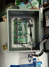
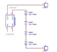
Hi everyone, I wanted to know if this type of 100 amp SSR with heat sink could be fine if used to connect/disconnect the positive of a 48V 70 amp storage tank. Furthermore, are they reliable and have little voltage loss?
My translation in picture. Voltage loss of SSR usually is between 1 to 1.6 volts. So if the load draws 35A, power loss in the SSR will be 1.6 x 35 = 56 watts.
SCHEMATIC1 _ PAGE1.jpg
 
Listen, the problem arises from the fact that I struggle to translate, but today I found that unfortunately the translation is poor. I'm sorry, I don't want to irritate anyone. However my need would be that in my photovoltaic system, made up of 1.4 kwp of panels, a 30000/6000 w inverter, an epever 6415AN, and 4 12v AGM type 110 amp batteries in series if I buy a 48v lifepo4 battery , how can I go from AGM batteries to lifepo4 batteries. I hope the translation does its job.
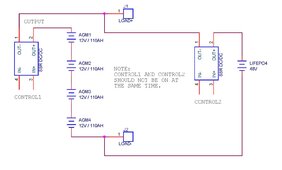
My translation in picture. I am not sure if I got this right.
SCHEMATIC1 _ PAGE2.jpg

Edit: I think the OP needs to do more than what this picture shows.
 
My translation in picture. I am not sure if I got this right.
View attachment 225079
Finally !!! That's what I thought I would do but I couldn't explain how to implement SSR. The fact of using SSR was for this purpose at least 2 SSR one for the AGM and the other for the lifepo4. Furthermore, in order to manage the two banks, I bought a dry contact to detect the voltage and make the contact to excite the SSR. In practice, the first example SSr connected to the AGM is primary and active, with the drycontact, when an example voltage is reached of 48 v, activates the switching which should energize the second SSR and turn off the first. In short, something like this to plan and design.
 
Just be careful with using 2 SSRs like a double throw switch. Usually they fail shorted and can cause a lot of damage.
 
Just be careful with using 2 SSRs like a double throw switch. Usually they fail shorted and can cause a lot of damage.
Ok, but using SSRs is only what I could think of putting into practice. But it is not the solution, if you have to propose how to replace the SSR I would be grateful. What and how can we do as an alternative?
 
I have a variation of that issue. I have a single controller charging lead acid battery in parallel with a lithium battery. The lithium battery only supplies the house. There is no back feed from the lithium to lead. I use the voltage drop of a diode and wire resistance to match them up pretty close. Occasionally I throw a switch to do some balancing. This only gets used 5 months a year. Even though I can do anything in electronics, I don't think I would let me get into your situation. Just too many thigs to go wrong.
 
I have a variation of that issue. I have a single controller charging lead acid battery in parallel with a lithium battery. The lithium battery only supplies the house. There is no back feed from the lithium to lead. I use the voltage drop of a diode and wire resistance to match them up pretty close. Occasionally I throw a switch to do some balancing. This only gets used 5 months a year. Even though I can do anything in electronics, I don't think I would let me get into your situation. Just too many thigs to go wrong.
Thanks for replying, and sorry again if I didn't make myself clear. Yes, it is actually just an idea to use an SSR, and the fact that you use such a system could be interesting. If you can make a small diagram of what you have I would be grateful. I'm trying to get more solutions to the problem.
 
After some thought, I think I would use an automated three phase transfer switch and modify it. This prevents two relays being possibly on at the same time. Then use the voltage drop of strings of diodes to prevent anything (charge controller or load) from being fully unloaded in the transfer. Maybe some PTC fuses to limit current too. Those details have not been worked out.
 
Last edited:
After some thought, I think I would use an automated three phase transfer switch and modify it. This prevents two relays being possibly on at the same time. Then use the voltage drop of strings of diodes to prevent anything (charge controller or load) from being fully unloaded in the transfer. Maybe some PTC fuses to limit current too. Those details have not been worked out.
Thanks anyway but it's starting to get more complicated for me.
 

diy solar

diy solar
Back
Top