diy solar

diy solar

Stalling Issue on turbine

Hogheavenfarm

Regulation Stifles Innovation
Joined
Jun 24, 2022
Messages
432
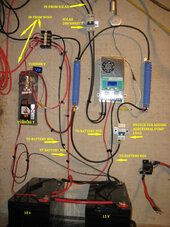
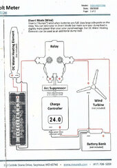
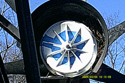
Finally got a weekend with good wind to experiment with the turbine, and was able to confirm its stalling under load. I disconnected the cables and the stiff breeze immediately started the turbine spinning up. Reconnecting them slowed it right down and stalled it. So I need to prevent the turbine from trying to charge until the voltage is higher and it has spun up. The DC output cables go directly to the battery bank, and the controller is connected in parallel off the battery bank, so it does not interrupt the circuit, just senses the voltage and triggers the dump load if it gets too high.
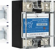
I have an old PWM I could connect the turbine output to, but it has a 50v input limit, so would likely fry in a good wind. I can't spend alot on a special controller, is there some way I could hook up a voltage sensor and a solenoid to stall off the charging until it hits 24 volts or so? The solar controller on the same bank will take up to 100v, but that would probably fry as well, I know the turbine can put out more than that, and that would start to get on the expensive side.
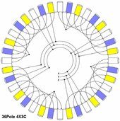
I am running a 5ft swept area with 7 blades, and it will spin up in the wind but rarely continues very long.
 
What type of alternator/generator is connected to the rotor? Do you have an electrical diagram?
 
4X3 Star pattern, 36 pole F&P motor, 3 phase into rectifier at the motor, 2 wire DC out. Enters the building and goes to dist block which feeds the batteries and the dumpload on the controller. Wind controller on the left side of pic (w /voltmeters) is run directly from batteries. Wind controller will activate dumpload at 14.8v. Solar controller is a separate system on the right side.
Designed to give 50v at 10 mph wind at 180 rpm, startup at 7 mph (unloaded).
 

Attachments

  • 36pole4X3C.jpg
    36pole4X3C.jpg
    74.7 KB · Views: 19
  • IMG_1913.JPG
    IMG_1913.JPG
    236.8 KB · Views: 20
You need a controller or get the current controller to not connect the turbine to the battery until the turbine voltage is above the battery voltage. That allows the turbine to spin up and then connect, as long as the wind is strong enough then it will provide charging to the batteries. As the wind drops and the voltage drops below that of the battery the controller should then disconnect the turbine so it spins up again. This assumes you have it all sized correctly.

A voltage configurable relay may help out by doing the switching and allow you to keep the current controller.

 
is there some way I could hook up a voltage sensor and a solenoid to stall off the charging until it hits 24 volts or so?
I think a simple Voltage divider circuit powering a transistor to operate an appropriately rated ice cube relay may accomplish want you want to do. There may be a not-so-sweet spot when the wind is just right that may cause relay chatter.
 
I think a SSR (solid state relay) would work with some tuning. The input is a wide range of voltage (3-32) and very low current (milliamps)
You would need to install a pretty high value resistor in series with the input, then connect that to the bridge rectifier output of the generator.
A potentiometer would allow you to adjust the generator speed the battery would start charging. Determine your generator dc open circuit voltage. Since yours is around 50 volts, start with a very high value resistor sized to drop the input voltage to less than 32. Once you select an SSR, look at the spec sheet for input milliamps. The correct resistance can be calculated from there. The output of the module connects in series with the battery. As soon as the output closes, the relay input voltage will fall substantially and the relay module output will start switching very rapidly. No harm, that is what they are designed to do. I am not sure what your generator current output is but select a relay rated at that. The low cost ones work well but are notoriously over rated. I would multiply your output current X 4 and purchase that size. The relay also need to be mounted on a fairly large heat sink. They get very hot and burn out without one. As always, use extreme caution when working around these voltages. Open circuit values can be very high.
 

Attachments

  • SSR.jpg
    SSR.jpg
    195.5 KB · Views: 5


Crydom is a good brand. They actually perform up to what they are advertised. SSR's are also very sensitive to surges from coil field collapse counter emf as well as polarity reversal. Practice with a cheap one.
 
good options, I guess I am on the right track. I will look into this, meanwhile more testing today as I have good conditions for it. this is how it is wired at the moment. Originally I thought the controller would let the turbine freewheel until charging voltage was reached, but with the turbine wired directly to teh batteries, I could not see how this would work, as it doesnt pass through the controller first. Mine is a 12v system here, and no water heater load, just two ballast resistors.
 

Attachments

  • mwas diagram dump  20231110.jpg
    mwas diagram dump 20231110.jpg
    159.6 KB · Views: 11
Originally I thought the controller would let the turbine freewheel until charging voltage was reached,
It should and probably does. The current is what slows the turbine and you don't have current until the turbine reaches battery/system voltage.

Edit: unless your dump loads or brake is malfunctioning (always on).
 
Last edited:
something is happening then, as disconnecting the positive feed allows the turbine to spin up just fine, but plugging it back in immediately kills it, even at very slow rpms where I know its not producing any voltage above the battery voltage. I did find an interesting issue today during testing, but even though it had the potential to cause problems, I removed it and still have the same issue. Pics will be forthcoming.
 
The load on the alternator is excessive. This is slowing down the blade outside its power band. Compare it to shifting a car into high gear too early.
Try this .... If you have any old fashion 120 volt filament bulbs in the 25 - 100 watt range, try putting one in series with the battery charging cable. Let it spin up as before then connect. The addition of the bulb will decrease the load on the alternator allowing the blade to rotate faster, allowing it to get closer to it's power band. Try different sizes of bulbs. The lower the wattage, the less load on the alternator.
 
This is what I found when I went to disconnect the feed today, certainly would contribute to stall today, pretty sure it wasnt there yesterday though...
 

Attachments

  • DSCF0001a.png
    DSCF0001a.png
    946.8 KB · Views: 24
  • bird nest.png
    bird nest.png
    1.6 MB · Views: 25
So on the bulb thing. Hook a bulb into the positive feed from the turbine to the battery, (and switch I take it?) So with the switch off it will spin up then throw the switch? I understand the load on the line part, lost a bit on the bulb. With the line disconnected it will spin up bulb or not, once connected the load overcomes it, adding a bulb would just add more resistance, no? Right now the only way to turn off the turbine is to disconnect an mc4 connector outside at the tower base.
 
So on the bulb thing. Hook a bulb into the positive feed from the turbine to the battery, (and switch I take it?) So with the switch off it will spin up then throw the switch? I understand the load on the line part, lost a bit on the bulb. With the line disconnected it will spin up bulb or not, once connected the load overcomes it, adding a bulb would just add more resistance, no? Right now the only way to turn off the turbine is to disconnect an mc4 connector outside at the tower base.
Yes, bulb in series with the battery, add a switch in series also if you wish. The bulb adds resistance which lowers the current flow.
Lower current results in less load on the alternator. This is not the final fix, just troubleshooting. Try different objects in series, filament car headlight,
soldering iron etc. until it stops bogging down.
The current is coming from the turbine. How is adding more resistance going to speed it up?
 
The current is coming from the turbine. How is adding more resistance going to speed it up?
It will at some point decrease the load on the generator. It is speeding along fine with the battery disconnected (open circuit), which is close to infinite resistance.
 
I will be trying it. I can only really work on it weekends, and it seems the last 6 months it has rained or snowed every weekend, this was the first good one in a very long time (see my prev posts), but I can fabricate a test line during the week and hook it up on the weekend, then I just need some wind. March is coming and thats when our winds are the strongest. After april they pretty much die out unless there is a storm.
Thinking about it last night, I may have designed the cut in speed too low. If I remember, I used a 60 rpm cut in, and thats about how fast the turbine was going for a while before it stalled, seemed slow to me until I realized that 60rpm was 1 rps. So maybe it is loading up right away. I guess I could always series the batteries and go to 24v and raise the cut in speed? (Probably not double, but increase it some.) I have one chart I made early on in testing, not real clear, but its all I have.
 

Attachments

  • Screenshot from 2024-02-05 08-23-52.png
    Screenshot from 2024-02-05 08-23-52.png
    38 KB · Views: 8
Back
Top