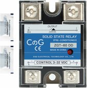
That high unloaded voltage might be problematic for the solid state relay across terminals 4 and 3.The SSR looks interseting but I know the turbine will put out more than 60v. something like this maybe better? 250VDC at 40 amps? I know its a bit overkill, but since this imported stuff has a high failure rate, staying away from full scale operation might make it last longer?
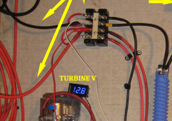
What would I trigger the relay with? I could parallel the turbine feed, but that would kick it in too low (3v?) The minimum voltage doesnt seem to be adjustable. I could use a solar panel (I have some 100w panels around) that would kick in around 20v or so, but only during the day.
An old school centrifugal rev limiter would work well, very steampunk.
This is a rough draft of a circuit if you want to sketch it up. I would test it on a bench not using the generator or your AGM cells to confirm polarity's are correct and the circuit functions correctly.
I've used alligator clip leads and 9 volt batteries, small chargers etc. in the past to test things.
Remove the turbine positive wire from the battery and connect to SSR terminal 2.
Connect new wire (same size) between SSR terminal 1 and the battery positive terminal.
Run small light gage wire between SSR terminal 4 and battery negative terminal. (insert 1 amp or less fuse)
The control circuitry (voltage divider or variable resistor) would connect between terminal 2 and 3.
Terminal 3 and 4 is internally optically isolated. I wish the milliamps thru it at 30 volts were listed.
This would make the resistor calculation easier. If the sun shines here on Saturday, I will measure the one I am using.
The SSR is designed so that terminals 4-3 and 1-2 are isolated from each other by separate voltages. I am not sure they have to be as the input is optical. They would not be isolated when connecting terminals 2 and 3 (and resistors) to make this work. The potential for over 30 volts being applied across terminals 1 and 2 is there, but it might never get to that level if terminals 1-2 internal switching happens fast enough. One possibility is to set that dump load controller to around 25 volts and connect it across the turbine terminals but... I don't know if your dump load controller can take that voltage and if the dump load solenoid can act fast enough. Since there is a risk of the SSR being damage during trial runs, I suggest putting a small 1 amp or less fuse in the wire between the battery negative and terminal 4 in case the SSR fails. Also heat sink the SSR. Some come with them. The faster they switch the hotter they get.
Permanent magnet generators can generate deadly voltage if they becomes open circuit or under loaded for any reason. Always use
caution, wear insulated gloves, don't ground yourself etc. and meters and leads rated for that voltage.