


You are using an out of date browser. It may not display this or other websites correctly.
You should upgrade or use an alternative browser.
You should upgrade or use an alternative browser.
Sun Trekker
- Thread starter Campin
- Start date

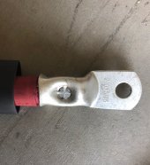
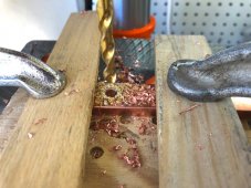
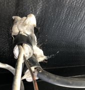
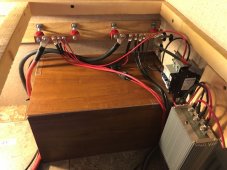
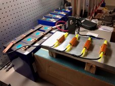
Making different length battery/inverter 2/0 cables.
Attachments
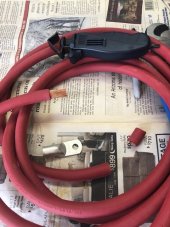
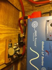
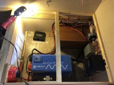
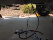
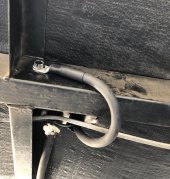
More wiring...getting there.
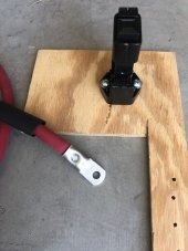
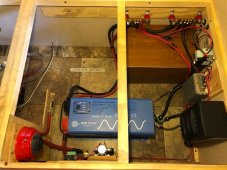
Positive battery 2/0 cable run: battery-battery fuse-cutoff switch-shunt (monitor system performance)-relay (safety shutdown)-inverter-positive busbar.
Negative battery 2/0 cable run: battery-inverter-negative busbar-chassis ground.
Positive battery 2/0 cable run: battery-battery fuse-cutoff switch-shunt (monitor system performance)-relay (safety shutdown)-inverter-positive busbar.
Negative battery 2/0 cable run: battery-inverter-negative busbar-chassis ground.
Attachments
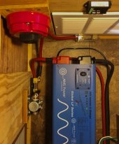
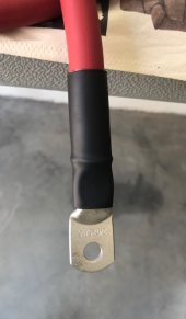
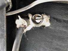
Solar system is (chassis) grounded. Luckily there’s an existing conduit (removed factory sealant) for 2/0 cable.
Attachments
Donlumber
New Member
- Joined
- Sep 10, 2021
- Messages
- 32
I might be mistaken but I thought RVs were grounded to chassis?As I wire a question pops up...the ac neutral busbar in my RV is isolated (no ground bond) so this is a sub panel, correct? That means shore power is the main service.
Thnx Donlumber for the info! ...yes chassis grounded. I didn’t understand why AC neutral wasn’t grounded at the RV. Then I learned my RV panel is a sub panel, meaning neutral is bonded either at the inverter or shore power source.I might be mistaken but I thought RVs were grounded to chassis?
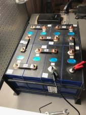
Solar battery update: Things are looking sunny ; )
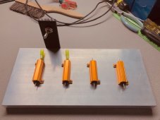
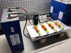
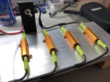
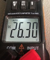
By discharging (kitty-corner) and passive balancing two (4 cell) banks, the difference between the banks is 1 mV, 2.570-2.571 (after numerous passes and discharge estimates). Next passive balance 8 cells overnight then discharge near 2.5V - bottom balance complete for my application...what a trip ?
By discharging (kitty-corner) and passive balancing two (4 cell) banks, the difference between the banks is 1 mV, 2.570-2.571 (after numerous passes and discharge estimates). Next passive balance 8 cells overnight then discharge near 2.5V - bottom balance complete for my application...what a trip ?
Attachments
Bottom balance update: Passive balanced for 4 days, it seems 8 cells will settle around 2.632 volts (began at 2.585V). My hope is all cells will be near equal voltage at 90% SOC...in other words no rogue cells. The idea may be faulty but worth testing.
If tests are successful, the battery can pretty much manage itself and little monitoring.
If tests are successful, the battery can pretty much manage itself and little monitoring.
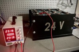
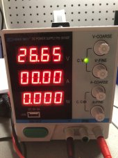
Now that the 8 cells are (passive) balanced, they’re connected in series and charging. The target voltage is 26.60V (90% SOC). So far so good, cells look tight (no bulging).
Attachments
Ampster
Renewable Energy Hobbyist
That is only 3.32 V per cell which is before the steep part of the curve. That is more like the resting voltage. But as you say they are bottom balanced so if you charge to that voltage you should have no issues. Are you going to use a BMS?The target voltage is 26.60V