diy solar

diy solar

Sunny Island Sunny boy conflicting info

Maitake

Solar Enthusiast
Joined
Mar 21, 2022
Messages
354
Hi All,
Thinking of doing this with (whole house backup + grid tie with transfer switch) 2SI and 2SB. I'll be grid tied with net metering 99.9%, and backup for the rest. I also want the option to go "whole house" off grid for extended periods if required.
2 things holding me back. SMA says 100AH battery is required for each kw of solar. Im not getting a 1000AH backup battery.??
The documentation also requires conflicting settings for on grid and off grid settings in the SB. Well this configuration is on grid AND off grid.
Also I understand the newer SB no longer have the comm cable to the SI inverter to tell it "slow down". Has the FSPC algorithm advanced enough to manage this?


Really like the product, but these unknowns are keeping me from pulling the trigger.

Thanks for any assistance.
 

Attachments

  • Screenshot_20220402-063509_Chrome.jpg
    Screenshot_20220402-063509_Chrome.jpg
    271.4 KB · Views: 19
Welcome to the Forum!

The following link lists compatibility for Sunny Boy use in grid-backup and strictly off-grid systems with Sunny Island.


Compared to previous version (which I don't find online any more), a couple inverters where changed regarding which applications work.
The series including 10000TLUS is no longer shown as compatible with grid-backup. The newer -40 and -41 models are now compatible with grid-backup.

A couple years ago, I bought old model 10000TLUS for that compatibility. In use, I found that while it didn't disconnect below 64 Hz, it didn't reduce output power so frequency kept swinging up until it disconnected. SMA support gave me the workaround of setting it in "offgrid" mode when used on-grid behind SI. They changed it in the updated list as no longer supported for grid-backup. (I would recommend not doing that unless you have and save a written message from SMA to do so, because it is not what documentation says. I envision possible failure modes presenting risk to utility linemen. I think the original scheme from SMA German engineers was failsafe.)


I also asked a couple years ago about use of the newer -41 models for grid-backup, because nothing currently available from SMA was shown as compatible. Now, those are in the list. SMA has also put instructions in a video with different recommendations.

Various marketing and video material from SMA has said standard UL-1471 inverters could be backed up with Sunny Boy Storage or with Sunny Island. Those GT PV inverters wouldn't respond to frequency shift, would just connect and drop offline every 5 minutes, and battery would cycle. I don't think that is a good idea, might damage something in the inverters as well as wear battery.

The new recommendation for -40 and -41 model SB in the compatibility list is to use CA Rule 21 (needs to have frequency-watts feature enabled).

"SBxx-1SP-US-40 / SBxx-1SP-US-40 with CA Rule 21 For SBxx-1SP-US-40 / SBxx-1SP-US-40 with set country data set CA Rule 21, the Sunny Island is able to curtail the power of these PV inverters via frequency-shift power control (FSPC) without a RS485 communication link. PV inverters without backup mode

For PV inverters without backup mode, the country data set must be set to the locally typical value for grid-tie PV systems as per UL1741. The PV inverter is then configured for operation on the utility grid. In the event of a utility grid failure, the Sunny Island is unable to derate the PV inverters by means of Frequency-Shift Power Control (FSPC). If there is an excessive supply of energy, the PV inverters will switch off."

Standard UL-1741 had tight frequency and voltage limits. That would stay online for in-spec grid and disconnect for 5 minutes if out of spec.

UL-1741-SA without frequency-watts rides through minor voltage & frequency excursions and remains connected for 5 minutes, then disconnects.

UL-1741-SA with frequency-watts ramps down power with increasing frequency, something like 100% at 60.5 Hz to 0% at 61 Hz. I'm not sure the limits where it would disconnect for a period of time rather than just coming back immediately when frequency drops.
I believe this was a firmware update to -40 & -41 inverters. Other brand inverters can also work this way. (You want frequency-watts.)

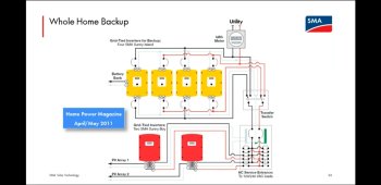
SMA's off-grid setting (or "island") by default ramps down from 100% at 61 Hz to 0% at 62 Hz, but those can be changed. It remains connected up to 64 Hz, ready to respond immediately if frequency drops. Above 64 Hz, it disconnects for 5 minutes. This disconnect is used to knock SB offline so it doesn't deliver power while SI resynchronizes to grid. Wider voltage variation is also tolerated. This allows generator with looser regulation to be used.

The RS-485 cable with piggyback that fits older SB allows SI to tell SB when to switch from standard UL-1741 parameters to off-grid parameters. If grid deviates from standard tight specs, SI disconnects according to UL-1741 (it doesn't have UL-1741-SA, but I would expect new model to do that when European model gets modified for the U.S.)

Because SI disconnects grid, it would seem SB offgrid settings would be sufficient. Some SMA material (e.g. videos) have said to use that setting. My guess as to why original designers and written documentation differs is that grid relay could become welded shut. Sunny Island would not be able to disconnect from grid. It would simply not signal by RS-485 to switch to off-grid parameters, and so SB would obey UL-1741 and shut off. But if SB was set to off-grid rather than grid-backup, it would keep driving through relay into grid without performing UL-1741 anti-islanding.

It looks to me like any GT PV inverter including SB -40 & -41 should work fine with UL-1741-SA frequency-watts mode for on-grid and grid-backup. If used with a generator, poorer voltage and frequency regulation may cause the to disconnect at times.

Because I have a "grandfathered" system originally permitted with SB 2500US before UL-1741-SA, I don't have to install the newer -40 or -41 models. I bought 10000TLUS, then switched to 5000US, so I am able to use RS-485. That is the way to go (and you might lucky and find new in the box old stock) if your locality doesn't require the inverter to have the "grid support" features of UL-1741-SA.
 
Missing from that diagram you posted, you want a "load shed" relay as described in SI manual. That disconnects all loads if battery low but leaves SB connected. By default, it disconnects at 70% DoD but SI keeps running down to 80% DoD. That lets SB recharge battery when sun comes up.

SI documentation calls for minimum 100 Ah, or 50 Ah if lithium.
It also calls for minimum 100 Ah per kW of AC coupled PV inverter.
This is probably so it can stuff power into the battery during the seconds it takes to swing frequency up and get GT PV power output reduced to match load.

I have 400 Ah of AGM with 10kW of GT PV. This seems to work fine. The load which normally cycles on and off is an A/C on 20A 240V breaker. I have, for testing purposes, powered 10kW of electric furnace.

Each SI can charge battery at peak rate of 140A. That's 7kW at 50V, 8.4kW at 60V. So it can absorb that much while swinging frequency, less whatever charge current it is already delivering. Battery needs to accept that, so maybe if using Li you should set max charge voltage a bit lower to allow this.

When you configure SI by quick-start, it sets maximum battery current to 0.55C. But if you follow guidelines of 100 Ah per 1kW of PV, PV can only deliver about 0.2C. So if you undersize battery, reduce that max charge rate to what you want. I set mine to 0.2C max, where my bttery is happy. Because my PV could deliver 0.5C, the extra 60% is curtailed if not used by loads. House runs PV-direct while battery charges at steady 0.2C
 
Instead of the transfer switch where shown in your diagram, you can use SI with its internal switch to support a protected loads panel. Up to 56A pass-through.
Actually, two panels. One connects straight to SI and has SB (plus any very small critical loads like alarm or internet box. Must be small enough to not drain battery to the point of SI shutdown overnight.) Then after a load-shed relay connect protected loads panel for refrigerator, etc.

Non-battery-backed loads like electric furnace remain on original main panel. Optional interlocked "generator" breaker would let you manually select to backfeed it from SI, after turning off excessively big loads.

Protected loads panel should have interlock so if SI fails you can manually switch it back to grid.

Sunny Boy (and critical loads) panel could also have such interlocked breaker. At least if you are relying on UL-1741-SA to support frequency shift, because it is compliant. If you use RS-485 for switching to off-grid mode, do not shift those Sunny Boys straight to grid unless you disconnect RS-485 so they are UL-1741.

If you do have a transfer switch which can cause SB (or SI) to toggle between two AC sources, e.g. SB switched between SI and grid, or SI switched between grid and generator, don't let it switch instantly. Input power to inverter must go away for 5 seconds before connecting second source, to ensure inverter turns off output and doesn't backfeed out of phase, which could destroy it. Manually interlocked breakers (of some models) are good for this because they require multiple manual motions. A few interlock models allow too-fast operation.
 
First I want to day thank you for being so generous with your knowledge.
Ima gonna have to digest all this and get back this evening.
 
After digesting that awesome information, I have come up with the following diagram which hopefully will work, or at least be closer to something workable.
The 560ah is lifepo4.
My utility is OK with CA rule 21 inverters. Will skip any rs485 comms.
Not shown on the diagram is a shunt and 48v charger to the secure power outlet for black start should that be necessary.

Not sure of the best feed location for the Sunny Boy?
Maybe direct into the protected load panel? There seems to be little benefit to attaching it directly to the Sunny Island.

If it looks good breaker sizing is next.....

Thank you again!
 

Attachments

  • 20220408_070506.jpg
    20220408_070506.jpg
    93.3 KB · Views: 11
After looking at the SB connection, if it's "off grid mode" it should connect to AC1 of Sunny Boy so I don't connect it to the grid with off grid settings. It's only path to the grid is via the 56A internal bypass relay.
That sound right?
 
I can get the pure off grid application of AC Coupling but when you add Grid Tied and a back up generator on a dedicated transfer switch it quickly gets my head spinning.

I'll be watching this thread to see if I can pick anything up as I'm in the beginning of something like you're doing.
 
After looking at the SB connection, if it's "off grid mode" it should connect to AC1 of Sunny Boy so I don't connect it to the grid with off grid settings. It's only path to the grid is via the 56A internal bypass relay.
That sound right?

SMA's written documents say to put SB in "country data set CA Rule 21", not off-grid mode, when used with Sunny Island on-grid.
In videos created by the US marketing arm, they may say otherwise. I do not have complete confidence in their technical competence or understanding of failure modes.
For utility lineman safety reasons, I prefer to do as the original engineers said.

 
I can get the pure off grid application of AC Coupling but when you add Grid Tied and a back up generator on a dedicated transfer switch it quickly gets my head spinning.

I'll be watching this thread to see if I can pick anything up as I'm in the beginning of something like you're doing.

It can electrify a village. Or a small country.
With AC coupling, you can distribute PV (and other) generation around your property.


There are smaller, more integrated and all-in-one approaches.
Multiple box approach can tolerate some failed units and keep operating. Failed Sunny Islands, in some cases it can operate through, and some (like master fails) you would have to reconfigure a slave to take over.

I prefer each module weighing < 150 lbs so I can move around with a dolly. For others, forklift size equipment is good.
I've got 1000 lbs of electronics and 1000 lbs of battery, but each piece is small enough for me to handle.
A single all-in-one unit like SolArk would be sufficient for some size systems.

Needing an external transfer switch is extra complexity. Some brands have that internal, with separate grid and generator inputs. I'm not using a generator, but I do use interlocked breakers as manual transfer switch so loads can be fed by either grid or Sunny Island.
 
After digesting that awesome information, I have come up with the following diagram which hopefully will work, or at least be closer to something workable.
The 560ah is lifepo4.
My utility is OK with CA rule 21 inverters. Will skip any rs485 comms.
Not shown on the diagram is a shunt and 48v charger to the secure power outlet for black start should that be necessary.

Not sure of the best feed location for the Sunny Boy?
Maybe direct into the protected load panel? There seems to be little benefit to attaching it directly to the Sunny Island.

If it looks good breaker sizing is next.....

Thank you again!

Sunny Boy landing on "critical loads panel" rather than "protected loads panel" would be the thing to do.
Critical loads like alarm, internet modem being so small they can run all night on 10% of battery capacity, along with SI no-load draw.
Protected loads big enough they might over-drain battery, so load-shed relay to disconnect them at 70% DoD (SI keeps running until 80% DoD).

Then maybe another load-shed relay between protected loads and interlocked back-fed breaker on main panel. Disconnecting those larger loads around 20% DoD, so they run while sun is out but don't run the battery down too far at night.

I have the second load-shed relay but haven't wired it in yet. For now, I manually flip the interlocked breaker connecting main panel as well if desired. I plan to have that 20% DoD also disconnect A/C thermostat and a relay for laundry, both on protected loads.

If you don't want an additional panel for "critical" vs. "protected" loads, the keep SB connected where it is before load-shed relay. Just add fuses for them.


For now you have 2x SI wired 2s.
If you ever expanded to 4x wired 2s2p, you could see the problem I had where current didn't split evenly between paralleled inverters when on-grid. My solution was different brand breakers on DIN rail for input and output rather than QO270.
If you use conduit, put a few extra "T" in them so you can easily branch off to yet another box, to hold breakers, fuses, relays, etc.


Maybe you can leave out the battery shunt if only DC coupled source would be battery charger for emergency black start. SI will figure out battery SoC eventually when battery is full. Besides, your BMS is going to track and report that.
I don't know how SOC based settings for shut-down and load shedding work with lithium settings. Presumably SI just gets SOC from BMS and functions work as before.
 
I was asking myself what my complicated diagram was getting me.
One sub panel that would never go down?
Not my priority.

Latest path is to run Sunny Boy to the main panel. Put Sunny Island on an interlocked breaker (like a gen set).
Run a small solar charger to keep the bank charged, but not too high, maybe 80%. The Sunny Island can charge it higher, it's more likely to get used if the SI is charging it.

When the grid is up, Sunny Boy sends power to it and the house.
When the grid goes down, I flip the main breaker off and the interlocked breaker on, start the Sunny Islands and have backup power until the sun stops shining or something breaks.

Any faulty thinking going on here?
 

Attachments

  • 20220408_170152.jpg
    20220408_170152.jpg
    87.4 KB · Views: 4
Ditch the extra charger stuff.
Sunny Island is supposed to be fantastic and charging and maintaining lead-acid.

Feed SI AC2 input from a breaker in the main panel.
If grid goes down, turn off that breaker and work the interlock to backfeed main panel from Sunny Island.

While you're at it, you can have AC2 go to your alarm, internet, whatever. It is a UPS (except for a glitch of maybe 30 ms during switchover.)
Optionally also put Sunny Boy on that panel.

Do you have neighbors? Once you turn off your main breaker, you have now way to tell when grid has returned, except by seeing your neighbor's houses lit.

(but some battery charger could be good for the dark start problem. Either after grid returns, or using "Secure Power" outlet of SB)
 
Ditch the extra charger stuff.
Sunny Island is supposed to be fantastic and charging and maintaining lead-acid.
It's lifepo4. I didn't want to "float" it forever, but maybe OK at 3.4-3.45v/cell?
Will use a REC BMS.
Feed SI AC2 input from a breaker in the main panel.
If grid goes down, turn off that breaker and work the interlock to backfeed main panel from Sunny Island.
If I forget to open the AC2 breaker before working the interlock to connect ac1 to the main panel, will it break the SI by connecting ac1 to ac2? I know it happens internally with the relay, but assumed it included electronic sorcery.
While you're at it, you can have AC2 go to your alarm, internet, whatever. It is a UPS (except for a glitch of maybe 30 ms during switchover.)
Optionally also put Sunny Boy on that panel.
I had no idea ac2 did this!
Do you have neighbors? Once you turn off your main breaker, you have now way to tell when grid has returned, except by seeing your neighbor's houses lit.
Powerco sends me a text when it's back on. Yes some neighbors in the distance, but not on the same circuit.
(but some battery charger could be good for the dark start problem. Either after grid returns, or using "Secure Power" outlet of SB)

Thank you so much.
 
If SI is fed from a breaker panel and feeds a breaker panel, one of two possibilities:

1) Input is in phase with output, so it goes through its wait and synchronize routine, connects to what it thinks is "grid", anti-islanding notices a problem, disconnects, repeat.

2) Input out of phase with output. Goes through its wait and synchronize routine, chases its tail, never manages to synchronize.

I don't think either is particularly harmful.
Closing the internal relay IS connecting AC1 to AC2.

"Load Shed" relay would be nice. SI AC1 drives SB & critical loads panel (which has interlock breaker to bypass SI and get power from grid instead.)
Feeding through load-shed relay, drive interlocked breaker on main panel.
Running on battery, SB and critical loads remain powered, but house is disconnected if battery gets low. That's what I've got, and the idea is no over-discharge, no black-start required.

My meter has its own breaker. Then after a cable there is breaker on main panel. Branch circuit feed (and backfed by) Sunny Island. Sunny Island feeds SB panel. Load-shed relay feeds house (which can switch back to main panel by interlocked breaker), and also goes to interlocked breaker on main panel.

So mine can also feed itself if I don't turn off a breaker.

Future plan is "line side tap" between meter breaker and main panel breaker. And 2-stage load shed.
 
Thank you for your guidance and sharing your in depth knowledge of these units.
I have enough info to get started.

Yes I will use a load shed relay, and have an alternate charging means in case a black start is necessary.
 
Back
Top