diy solar

diy solar

Sunny Boy 120V operation (for 1x Sunny Island)

Hedges

I See Electromagnetic Fields!
Joined
Mar 28, 2020
Messages
20,682
I was excited to learn that Sunny Boy SB xxxTL-US-41 operate at 120V.
Sunny Island 6048US is 120V, and SMA hasn't offered 120V Sunny Boy since the SB 700 ... SB 1800. So 2x SI or transformer needed to connect SB.


Then @Solarisium accidentally connected his -41 to 120V from the grid, and it worked!


Earlier model SB could auto-select 120/240V split-phase, 120/208Y, or 277V single phase by voltage and phase between L1, N, L2.
The -41 model does not support 277V. It does have 120V "Secure Power" batteryless backup.
It appears that if -41 is wired they way earlier 277V inverters were wired, it operates at 120V. Still TBD if it does frequency-watts, needed for well-behaved AC coupled off-grid or backup system.

I've since picked up an SB xxxTL-US-41 and an SB XXXTL-US-22. Both operate on-grid at 240V.


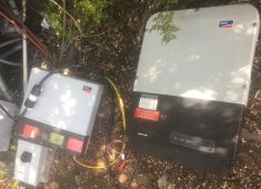
I tried to do 120V by tying N to either of L1 or L2. SB -41 just blinks on and off with either connection. SB -22 reported grid fault in one configuration, waiting or voltage in other.

SB 120V test IMG_3921.jpg

@Solarisium, how did you connect L1/N/L2? I can't seem to reproduce your results.


I'm now thinking I'm supposed to float N, not connect it.
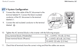
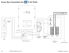
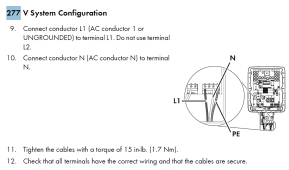
no? RTFM usually works. It (manual for SB xxxxUS) says to connect N but not L2.
I've now tried almost everything.

1688238722414.png


1688238801292.png

1688238982843.png


Anybody got other ideas??
 
I was excited to learn that Sunny Boy SB xxxTL-US-41 operate at 120V.
Sunny Island 6048US is 120V, and SMA hasn't offered 120V Sunny Boy since the SB 700 ... SB 1800. So 2x SI or transformer needed to connect SB.


Then @Solarisium accidentally connected his -41 to 120V from the grid, and it worked!


Earlier model SB could auto-select 120/240V split-phase, 120/208Y, or 277V single phase by voltage and phase between L1, N, L2.
The -41 model does not support 277V. It does have 120V "Secure Power" batteryless backup.
It appears that if -41 is wired they way earlier 277V inverters were wired, it operates at 120V. Still TBD if it does frequency-watts, needed for well-behaved AC coupled off-grid or backup system.

I've since picked up an SB xxxTL-US-41 and an SB XXXTL-US-22. Both operate on-grid at 240V.


I tried to do 120V by tying N to either of L1 or L2. SB -41 just blinks on and off with either connection. SB -22 reported grid fault in one configuration, waiting or voltage in other.
View attachment 155338

@Solarisium, how did you connect L1/N/L2? I can't seem to reproduce your results.


I'm now thinking I'm supposed to float N, not connect it.
no? RTFM usually works. It (manual for SB xxxxUS) says to connect N but not L2.
I've now tried almost everything.
View attachment 155324


View attachment 155325

View attachment 155328


Anybody got other ideas??
I am only seeing this post now! Sorry, I didn’t login for 8 to 9 months.

To answer the question of how my inverter was connected to 120 V, I have to look at the posts I sent at that time. I don’t think my memory is reliable now.
This is what I remember: I connected five modules in series together and positive and negative wires were connected to the DC port of the inverter.
The inverter and the modules were all on the ground in my backyard away from the main Service panel, which is some 30 to 40 feet away.
I have a GFCI outlet nearby. I plugged in an extension cord, then two wires to go from that extension cord to AC of the inverter. Recall whether I used L1 and L2 or I used L1 and N. I want to say I connected to L1 and N.
I turned on the DC disconnect on the side of the inverter, and after a few minutes it connected to the grid. I remember that I went to the service panel and I looked at that small triangle or arrow small LCD of the meter that shows the direction of power. It was exciting for me to see the power flows back. Hence, I remember that.

This experiment was done in the first 10 hours of the inverter operation time. I believe I later repeated this the inverter was near the main service panel.


The inverter through some error messages when I was connecting and playing around with the connections. The error messages are still logged there but I don’t remember which error message corresponded to what type of connection.

I also remember that I was expecting to see 5×40 V equal 200 V on the DC side of the inverter but I only saw approximately 120 V DC. at that time I thought it’s because the panels are not tilted properly, so did not scrutinize that.
There was no rapid shot device connected to the modules at this point.

Later, when I watched more videos and read more posts, I learned that the inverter should be connected to 240 V AC rather than 120 V AC.
I thought the reason for observing a low DC voltage from that first experiment was that I connected the inverter to 120 V AC.
Fast forward after installation of all PV modules and all nine modules were connected. The DC voltage was floating around between 240 to 270 V DC and occasionally 320 V DC.
I was expecting 360 V DC from the nine modules.
Then I started asking around and I learned from you that inverters are not supposed to connect to 120 V AC.

The inverter was commissioned using 240 V AC after that incorrectly connected initial experiment.
I tried to reproduce the 120 V grid connection at a later time but received an error message saying grid incorrect grid voltage or something in that language.
I was take a look at the very first error messages and post them here later.

Ps. This post was entered using Siri please excuse typos.
 
Last edited:
Interesting that when you later tried 120V it didn't work. Same situation as mine, previously commissioned at 240V.
I hope there is a way to reset it back to working, or maybe it was wired differently.
Would be very nice to have a 1x SI, 1x SB system (without needing auto transformer.)

I'm thinking that L1 and L2 terminals of SB have to be used, not N, because I think N is only monitored to see voltage of each line independently. I don't think there is hardware to deliver power to it.

Separately there is Secure Power connector for 120V output. I think its L & N terminals map to same inverter circuitry as grid connection L1 & L2 (which are relay isolated from inverter, but connected to monitoring electronics.

My SBS has a menu setting or either 120V or 240V secure power. After all, inverter is capable of 240Vrms, just operated for lower 120V. I wonder if it would deliver same 15A at 240V for 3600W. I haven't connected or seen menus of SB yet.
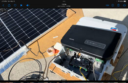
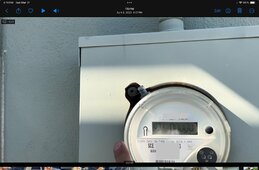
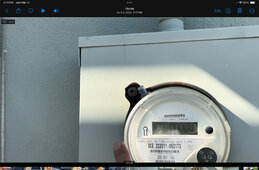
I found the video I shot on the day of commissioning. Sending some screenshots from that video. This is the first couple of hours of commissioning, meaning the 10-hour window was still open.
IMG_0581.jpeg
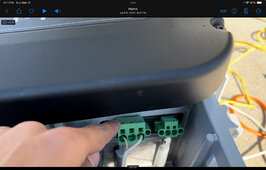
Confirmed that I plugged two wires to a 120v GFCI outlet, and connected them to L1 and L2 of the inverter’s AC block.
IMG_0579.jpeg

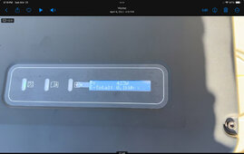
Confirmed that it did generate power. Some 435 watts from 4 panels laid flat, half shaded, at around 4 pm.
IMG_0580.jpeg

And confirmed that at that time it exported at least a portion of it to the grid. Notice the triangle pointing to the right (grid
IMG_0582.jpeg

Hope this helps. Looking back at this, I laugh at my level of ignorance that I connected the inverter to 120v, neutral to L2, many other things not shown here! Makes me appreciate German engineering in this equipment and how solid it is!
 

Attachments

  • IMG_0582.jpeg
    IMG_0582.jpeg
    184.8 KB · Views: 3
Back
Top