diy solar

diy solar

Surge protection for PV panels and proper grounding.

Perhaps this is true for the all in ones. But don't think it would apply to seperate inverters and sccs.
Yes, I think that's right. I haven't thought about the separate option.

I worry more about static charge buildup than an actual strike.
Rain around here during summer can cause a surprising amount of static buildup on ungrounded wires.

For my outdoor PoE camera network, I use gas discharge tubes on all of the RJ-45s coming into the house, along with conventional MOV devices inside.
Did you built your own, or do you use commercial devices? I recently found out manufacturers of PoE SPDs are seriously overpricing their products. To the point of $100 for 4 ports for the cheapest option (only mov's, no GDTs, $150 for both).

So I'm considering DIYing it.
I’m not sure there is a universal “right” answer, but I appreciate the thought you’ve put into this, thanks.
Thanks
 
@timselectric - the expert on all things to do with ground

He would say 'There can be only one' - meaning one grounding system and everything is attached to that single grounding system.

So, in the case of the remote array when the lightning strikes near the whole system attached to the house ground raises by many thousand volts at once because they are connected to the house ground. No difference of potential so no damage. A few microseconds later the house ground is raised by many thousand volts. No difference in potential so no damage.

It is unfortunate that the array mount is grounded by virtue of being in concrete in the ground, but there isn't anything you can do about it. To avoid a difference of potential when touching metal frames of panels and the racking you MUST attach the racking to the EGC from the house.

A lightning strike has a great deal of voltage and not much current - so the EGC connecting size just needs to be the same size as is used for the PV lines.

And the recommendation stands - SPD at both ends if the distance is more than 30ft
 
Did you built your own, or do you use commercial devices? I recently found out manufacturers of PoE SPDs are seriously overpricing their products. To the point of $100 for 4 ports for the cheapest option (only mov's, no GDTs, $150 for both).

I get the devices for POE and other signaling wires that run outside from l-com - I get the ones that are 3 stage - GST (gas discharge tube), FET, TVS diode -


I've had a number of them blow up and never lost attached equipment.

For the pv power lines I will use the midnight solar SPD which appears to contain a GST among other things.
 
Did you built your own, or do you use commercial devices? I recently found out manufacturers of PoE SPDs are seriously overpricing their products. To the point of $100 for 4 ports for the cheapest option (only mov's, no GDTs, $150 for both).
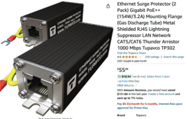
I use these:
Screenshot 2024-06-10 at 11.41.10 AM.png

Though I don't know why Amazon thinks Thunder can be arrested.:)
 
Last edited:
I use these:
View attachment 221061

Though I don't know why Amazon thinks Thunder can be arrested.:)


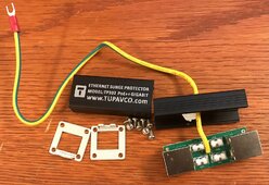
With a translation error like that I would be worried about them having anything inside the case except 8 wires going straight through. Ever look inside to see if they have a GST or any other electronics to prevent surges?
 
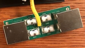
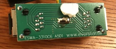
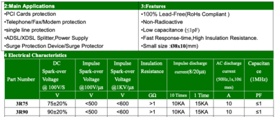
IMG_6739.jpg IMG_6739.jpg IMG_6740.jpg

GDT Markings: 3R90
Looking for Chinese data sheet.
These are apparently rated 90V 10 kA

No apparent Thunder attenuation though 🤪
No plastic, case is all anodized aluminum. Pretty well constructed.

Screen Shot 2024-06-10 at 3.54.02 PM.png
 
Last edited:
Basically 4 x center grounded gas discharge tubes - That should be a good start -
Yes, these are outside the house in a junction box.

I have traditional MOV-based PoE power supplies inside the house.
And then the UniFi PoE++ switch has its ESD protection as well.
 
Back to the topic -

Dualing SPD the op was concerned about - they would both be trying to short over-voltage to the grounding system. So there is no dual - if either sees voltage over the rating it will go into a shorting mode. Then if the other end sees the same they would probably both going into a shorting mode. Either way they both do what they are supposed to do and you loose a few seconds of power because there is a current short across the PV and as long as you sized the wires correctly to start with there is no problem.

Having the SPD close to both ends and a EGC between to attach them to keeps you from picking up energy in the long lines between.

Now a lightning strike that burns through insulation is going to be a problem no matter what you have.
 
Depends on the class/type. Class 1 - agreed 100% these are to protect wiring insulation from breakdown. Class 2.. Mhmm they will protect induction motor windings, some robust electronic devices etc. Class 3 - these do protect electronic devices assuming the devices can withstand 2x the normal voltage for a long time and 3x momentarily.

Are there plenty of devices that die when you exceed their voltage by 20%? Probably, but saying SPDs protect mainly from fire is incorrect.


I'm not sure how that would help, or where to put it. In general the goal when talking about dissipating surges is to lower inductance as much as possible to prevent high impedance to dissipate the surge current.

I suspect you mean an opposite. Increase impedance to present a sort of barrier to surge current, but how do you know the sign of overvoltage, or which conductor it will come from? In such case lowering inductance of everything is the safest IMO.

So scenario 3. The war of SPDs... 🙄

However I now had another idea, or a realisation. Mike Holt and others alike always talk about connecting it one place. I though what they mean is bonding it to neutral which is done at one place(the main panel) . But perhaps what they mean too is connecting the grounding electrode (including auxiliary electrodes) with system ground in only one place.

So to achieve this I'd need two grounding wires at my array. One is system ground that I connect SPDs to. The other is the conductor that ties the ground mount to the main system ground.

This has an adventage of offering some protection to everything. Still local ground can go very high and system ground will reflect some middle ground(no pun intended). This is less than ideal, but doesn't leave anything unprotected.

I'm not sure. What do people that live in places with lots if lightning do?
People in North East Florida and South East Georgia (the lighting capital of the U S) have good insurance...our boat go struck 3 times there!
 
People in North East Florida and South East Georgia (the lighting capital of the U S) have good insurance...our boat go struck 3 times there!

Sadly it is not an option for me :-( I've looked into insurance. No one will insure a DIY system in my country (Poland). Not even from things like hail, or theft/vandalism. It is beyond stupid, but every Ts&Cs of every insurance provide I read has a statement "Equipment must be installed by properly certified installer". It doesn't matter there is no certification nor any qualification required in any local code/laws for off grid systems. They still have this stupid rule and they will use it to decline any claims. Even if your panels get hail damage or get stolen.


BTW, I found this article very helpful: https://www.eaton.com/content/dam/e...arthing-surge-protection-application-note.pdf

After reading this I now have another question? If a star shaped grounding is impossible is what they call a "remote outstation installation" the next best thing, far better than connecting all the local grounds with a cable and have this "serial ground" for a lack of a better term?

Just to clarify, what I call a serial ground is imagine few buildings (or 2 buildings and a solar array). Each building and the array has its own ground. All 3 grounds are connected together building 1 to building 2 to the solar array.

Star shaped ground is self explanatory. In an ideal world everyone would have it.

The "Remote outstation" is essentially a separate building(or an array) that has its own ground not connected to the main system ground and you have SPDs fitted on all connections between it and another building.
 
Last edited:
I caution against adding inductance. Inductors tend to create voltage spikes when the current changes. If a surge comes down the line, the inductor current will be spun up, and when the surge ends, that will result in elevated voltages, perhaps even severely negative.

Mike C.
I'm not an EE...
So please help me understand this.
With inductance we are going to get a slower rise in voltage which should give SPD more time to react.
I am thinking a large ferrite donut with few loops on each leg.
Once the SPD conducts there is no reason for inductor to have additional impact.
It will store some energy over the voltage rise time and will release when the spike is over.
With both SPD and inverter conducting there is no reason for inductor to CREATE additional spikes.
It will extend the time with high(er) current though.

What am I missing?
 
That is what I was planning to do for my three strings but I am concerned they do not conduct heavily enough. The current versus applied voltage curve for MS DC SPD devices:

View attachment 220841

The MNSPD600 doesn't really start to conduct until 1000 volts, and it takes 1200+ volts to get solid clamping of a large surge. For an inverter with a 500 volt max MPPT rating, that seems like not enough and I could easily see damage occurring. This would mean your investment in SPD was really no useful.

My strings max Voc (temperature corrected) will be 401 volts. This makes me wonder if the MNSPD300 device would be better. The spec sheet says the 1 mA current occurs at 423-517 volts for the 300 volt device, so that seems like it would work and it would clamp much harder than the 600 volt device. 1 mA at 401 volts is 401 mW which is something the device could handle indefinitely, and the curve above implies it will be less than 1 mA. This would be using it outside the "nominal" voltage range in the spec, which seems risky somehow.

Mike C.

The purpose of SPD is not to limit voltage to allowed maximum of electronics, just to reduce it to something less excessive. It can only do that for very brief spikes.

Electronic systems have to tolerate spikes to several times their rating, but can only handle it briefly. The energy deposited causes heating of parts like transistors when it breaks down through semiconductor junctions.

A device designed for 120Vrms or 240Vrms would be tested with spikes of maybe 2000V peak.

Testing with bursts 5ns pulses to 500V ... up to 4000V


That's one of many qualification tests, including power line surge, sag, dropout, etc.

SPD start clamping, reducing voltage magnitude at a few hundred volts and reduce higher voltage spikes hopefully to less than the 2000V or so the devices can withstand.

A resistor divider drops some voltage across each resistor. SPD work similarly. If a 10,000V spike comes down the wires they might carry 5,000A for a microsecond with 2000V across them, and impedance (resistance + inductance) of wires drops the other 8000V.
 
Would be nice if someone had access to testing equipment to destroy a SPD by over voltage and then take it apart... I assume SPD are destroyed after one hit.
 
They can take multiple hits, I think more total Joules a little at a time, converted to heat.
Not clear to me whether or not they are consumed eventually by that or just dissipate heat like a resistor. Maybe doesn't distribute current uniformly and always chews away some parts.

To make a controlled amount of energy I can use HyPot to charge microwave oven capacitor through diode. I've used knife switch, haven't set up electronic (transistor switched) pulser but have one from salvage yard.

What I don't have is F/A equipment like diamond saw and SEM or microscope. I do have an IR microscope, however.

I don't think understanding damage to SPD is as interesting to us as its clamping characteristics, which are just voltage & current measurements. I can do up to 3000V from ground at 50 MHz and up to 2000A at 20 kHz. No high current high frequency (well, a shunt could work, needs to be low inductance.)
 
I'm not an EE...
So please help me understand this.
With inductance we are going to get a slower rise in voltage which should give SPD more time to react.
I am thinking a large ferrite donut with few loops on each leg.
Once the SPD conducts there is no reason for inductor to have additional impact.
It will store some energy over the voltage rise time and will release when the spike is over.
With both SPD and inverter conducting there is no reason for inductor to CREATE additional spikes.
It will extend the time with high(er) current though.

What am I missing?
Inductors create voltage spikes when the current changes. See:


If, say, you have a loose connection on your panels, the inductor will make the sparking at the joint much worse when the current goes to zero. That will cause the voltage to pike up until it arcs.

If you want to slow down things, put caps across the leads. The caps slow down voltage rise by absorbing the energy and then releasing it slowly. A combination of a resistor and capacitor is called a snubber circuit because it snubs voltage spikes.

The only caveat is to make the cap small enough not to affect the MPPT optimizing function. You are unlikely to provision such a large cap.

Mike C.
 
They can take multiple hits, I think more total Joules a little at a time, converted to heat.
Not clear to me whether or not they are consumed eventually by that or just dissipate heat like a resistor. Maybe doesn't distribute current uniformly and always chews away some parts.

To make a controlled amount of energy I can use HyPot to charge microwave oven capacitor through diode. I've used knife switch, haven't set up electronic (transistor switched) pulser but have one from salvage yard.

What I don't have is F/A equipment like diamond saw and SEM or microscope. I do have an IR microscope, however.

I don't think understanding damage to SPD is as interesting to us as its clamping characteristics, which are just voltage & current measurements. I can do up to 3000V from ground at 50 MHz and up to 2000A at 20 kHz. No high current high frequency (well, a shunt could work, needs to be low inductance.)


Well I agree to a point -

What I don't understand is how an electronic device can have a finite pool of joules it can disipate then it is done.... you either exceed the voltage/current or you don't. If you don't it should keep working just as well until you do exceed them.

So I am curious how something can be gradually eaten away and fail.
 
Coil both PV+ and PV- together and/or put both through a ferrite core or iron core or wire (with suitable polarity) through two windings of a transformer.

That is called a "common mode choke". It will have higher inductance to something which drives both wires high together (ground elevated voltage due to lightning, current from lightening strike coupled into both wires.) That reduces voltage/current driven on both simultaneously from reaching inverter.

They still allow differential current transients to flow in opposite directions, like SCC draws a pulse of current (should have been filtered by capacitor.) And it won't protect against differential current/voltage induced in the array by lightning, where a loop is formed by panels and wires connecting them. (look up what "twisted pair" is and try to configure like that.)

 
Well I agree to a point -

What I don't understand is how an electronic device can have a finite pool of joules it can disipate then it is done.... you either exceed the voltage/current or you don't. If you don't it should keep working just as well until you do exceed them.

So I am curious how something can be gradually eaten away and fail.

Right, energy deposited heats the semiconductor. Too hot does damage.
In the case of transistors, they have diffused doping. At elevated temperature, I think dopants migrate, changing characteristics.

But consider parallel fuses. Current doesn't divide evenly, so you might blow just some fingers. There's a video here somewhere of a guy blowing a 5000A fuse with current from a capacitor, but only some of the parallel elements get blown.

Same goes for ESD devices on ICs, laid out as interdigitated fingers.
Or multiple vias between layers, especially for aluminum which has a habit of metal-migrating.

You know the discussion of balanced wiring to parallel battery strings? Same applies to parallel fingers of protection devices.

MOV is probably Z-direction conduction through a disk of material. But the leads both come out same side. High current zaps probably crowd into one edge. Maybe if they came out opposite side it would distribute more evenly.
 
Well I agree to a point -

What I don't understand is how an electronic device can have a finite pool of joules it can disipate then it is done.... you either exceed the voltage/current or you don't. If you don't it should keep working just as well until you do exceed them.

So I am curious how something can be gradually eaten away and fail.
I agree with you as I don’t understand how but it seems to be the way it works…

They do cumulatively wear out unless a whopper surge takes it out at one time…

This was explained to me on the phone by the head dog at the hughes company who puts out the Watchdog series of SPD devices for RVs …
it was also explained on the phone to me by a tech at MS who makes the multiple SPDs I have on my PV system…( seperate from the RV.)

On the MS units if the blue lights are still on you still have protection …but if they go out after being used a while they have been used up and need replacing..) I have not had issue with any of the MS devices after at all… so I can’t speak to how often this could happen…probably depends how often it take a small hit ….or a big one…dunno.

I use two per array , both at the array…. and at the gear shed entrance …and every other wire entering the gear shed ..they all connect to one central grounding point.
That’s the best I can figure to do..

On the watch dog SPD device ( 50 amp) version , it is a much heavier ,expensive and more robust SPD ..
It protects the RV that’s plugged into it…and it did great for the first 4 years I owned it…

But like the MS device once it has used up the MOV protection it will flash an error code saying there is no more protection…it will work with no protection left but there is no protection for downstream circuits.

you can replace protection by swapping out protection modules yourself , so I bought a couple of the modules as spares….35 bucks ea..I have never replaced a module …I never needed to.

If a strong enough surge hits your wiring ,as it did to me when the power company guy came out and went up the pole and disconnected the power it created a large arc …I dint know what he did but it made a racket and flashed.. I think he screwed up somehow trying to hurry , not sure what he did…….l

I didn’t know he was doing it and had about 30-40;amps of 120 ac load running in the RV .. I would have turned stuff off and disconnected it all but he just rolled up and went up the pole and Bammm

It killed all power and it also killed my watch dog TOTALY…

Once the power was restored it refused to come on and work and blinked an odd error code…

The RV was un damaged but the Hughes had killed itself in its efforts to protect .

I called the huges company and explained…
He sent me a new unit , “no charge” , and he explained a lot about how they work…

They do wear down in protection… ..OR , if it’s a large event or close lightning surge it may totally use it all up in one event……sometimes it not survive… but it will probably save your property , unless it’s a direct strike, then your probably screwed

Mine didn’t survive but it stopped any damage to an sorta new RV.…

It’s been 4 more years since then and the replacement unit has worked great when surges and strikes have knocked out devices on the property but not under the Watch dog circuit. It has saved me several times when everything around me got a zap except the RV…and we’re all on the same grid connection..
I think they are great units ….

On a side note , I have missed see mentioned here , Both the manual, videos for MS units and verbal discussion with them on the phone stress not to let the 3 wires from the unit touch any other wires after being installed ……I had mine zip tied to be neat and orderly … evidentially I was wrong…

So now they are pretty much free floating or separated from other wires..

From what I have read and was told if a major strike comes in near the equipment the wires will possibly vaporize ( there words not mine) ..this can cause damage to other wire or material touching them and cause other problems..

As I have stated in previous posts.
I don’t really understand lighting real well and I don’t like it at all.

J.
 
OK, that explains a lot about them then.

I see MANY SPD that are din mount and use a mini busbar at the top to ground then the bottom is loaded with the panel lines. They all seem to have replaceable modules on them so they can be easy to swap out.

That is one thing I don't care for on the midnite solar, the form factor is odd ball verse being compact and din mount. And apparently the blue light is excessivly bright if I read reviews.

I bought a UL listed variety for about 1/2 the cost of the MS version. There are a ton of cheap ones but only a couple UL listed.
The only MS one’s I own are the Blue light clear dome model..
I have 8 115v ones and 2 300v ac ones ….they are about a hundred bucks each…

The blue lite is hardly bright on mine… Haa…..I like em …. It’s a plus to be able to see at a glance they are in good working order ..I wish they had blue tooth signal

The Hughes unit is bright as could be..when operating normally the outline of the bulldog face is a bright white …visable from 200 ft …when somthings wrong it goes to bright red…that means you should check the error message on the front.
The Hughes has a very strong Bluetooth signal and useful info screen .it will also cut off power if readings are outside of normal or shorts or low or high voltage..or whatever…

J..👍
 
I'm much in favour of cheap, but certified SPDs. Here this means various local rebrands of Chinese products. The "brands" on them will buy the Chinese stuff. Test it,vand if it passes they'll sell it under their own name. If it meets the class 1/2/3 requirement it is good enough for my equipment.

I only buy DIN rail mountable swappable ones. I really like the ones with remote readout, but they cost a lot more. I'd rather buy 3x the number of cheap(certified) ones than 1 expensive one.

Coming back to the inductances and common mode choking. There is no common mode choking of a surge large enough to overwhelm a class 1 SPD. The magnetic material will saturate very quickly and let everything from then on through...

Also, it is not common mode voltages that cause fires and destroy equipment. In the paper I linked earlier it is well explained how it is perfectly possible to achieve good surge protection even with crappy grounding providing it is single point grounding and you put your SPD there it will lift both legs of the system together. Unless there is a better path to ground somewhere itvwill do no harm. It is the difference in potential between live/neutral/ground that kills equipment, causes arcing, etc.

Now,the above is true for "normal" situations. Like a lightning strike nearby. If the same house gets hit... All bets are off. The air itself may provide better connection to ground at such high voltages than your serpentine ground wire. In which case we see side flashes (people standing next to metal things get injured)etc.

Then about testing. There are no special components in SPDs. All have one or more of:
-a gas discharge tube
-a mov (metal oxide varistor) prefferably big
-pin diode and a MOSFET (rarely)

All the above are available for relatively low voltages so they can be tested by a DIYer, but all have well known characteristics which are often given in the datasheet.


Unfortunately all of them are sacrificial so SPDs have to be replaceable easily andvtgey need indication if they are dead.

Gas discharge tubes blow up, MOVs get "used up". Pin diodes and MOSFETs die once the higher rated components (mov and tube) give out.

The best way to " test" your surge protection system is up to scratch is to have copper Ethernet network between multiple buildings and wired CCTV cameras on steel poles high up. Then have a storm...

Conputer network surge protection is different, but follows same principles.
 

diy solar

diy solar
Back
Top