diy solar

diy solar

Switch between Grid power and Solar power AND use grid backup

EscapedAritst

New Member
Joined
Oct 2, 2021
Messages
31
Location
Costa Rica
I am building two homes that now have two similar solar systems. Each has four eg4 6500ex inverters (with pv and batteries, of course). One of these two systems is backed up by the utility and the other by a generator. My question is basically the same for both utility and generator backup power.

1. I run in SBU priority.
2. When the batteries are low, I want the utility/gen to charge them as well as supply loads (especially in the case of the generator version).
3. I want to be able to disconnect the solar system entirely and have the utility/gen supply 100% of the loads (for servicing or system failure).
4. I want a non-technical home owner to be able to make this switch.

So, it seems that a manual transfer switch would have to do three things.

1. Disconnect the inverters' output to the house
2. Disconnect utlity/gen's input to the inverters
3. Connect the utility/gen to the house

I'm pretty sure the first two above need to be successful before the third is connected. Does such a switch exist? It must but I can't find anything. Any help on a manual switch between a solar system and utility/gen would be appreciated.
 
You just need a single transfer switch.
It will select between grid/generator or AIO's to feed the house.
 
Can you point me to the transfer switch you are referring to?
There are several options.
Automatic and manual.
But you need to size them for the loads that they are controlling. (30, 60, 100, 150, 200 amps)
You wire two inputs to them. (Grid/Gen and inverters)
And one output. (Loads panel)
Figure out what size you need. And they can be found everywhere. (Amazon, Ebay, electrical suppliers, and hardware stores)
 
So, it seems that a manual transfer switch would have to do three things.

1. Disconnect the inverters' output to the house
2. Disconnect utlity/gen's input to the inverters
3. Connect the utility/gen to the house

I'm pretty sure the first two above need to be successful before the third is connected. Does such a switch exist? It must but I can't find anything. Any help on a manual switch between a solar system and utility/gen would be appreciated.

"Disconnect utlity/gen's input to the inverters" does not necessarily have to be done before "Connect the utility/gen to the house".
Only issue would be if it's battery charging load plus house loads were too much for the generator.

That leaves you simply needing a switching device that can power the house breaker panel by eiter inverter or utility/gen, but never both at the same time.

A "transfer switch" as Tim says. Or an interlocked "generator" breaker in the breaker panel.
(But neither would also disconnect input of inverter.)

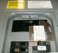
Here is one I use. Up to 225A main breaker, up to 125A backfed breaker, in QO panel.

1698150920497.png

Have a diagram of the inverter input and output connections, breaker panel(s), utility or generator input?
How easily any switch gets integrated depends on that.

I initially had the main panel feed my inverter by means of one breaker. (GT PV only, then battery backup for a protected loads panel.)
Then I added this backfed breaker, so I had to turn the input breaker off first or it would try to feed itself, and it still couldn't function as a UPS.
Finally I fed it from a line-side tap, so I can leave the panel fed by the (grid interactive) inverter for automatic backup (or manually switch to grid.)
 
Only issue would be if it's battery charging load plus house loads were too much for the generator.
Thanks both of you for your comments!! I can't see the png image in Hedge's comments, but I've considered the interlock solution. But as you mentioned in your reply quoted above, it seems to me that charging the batteries at the same time as servicing the house would, almost by definition, be too much even for the grid connection. But maybe I don't understand how this works.

I have 2/0 aluminum wires feeding the house (and inverters) from the grid. That is enough for 120 amps on each pole. I have 4 inverters connected from a busbar to this grid/gen connection. It seems if the batteries were low enough to demand the grid/gen, they would use that entire limit just to charge the batteries. Having the house on the same circuit, would be too much.

So, this being said (and if my assumptions are true), I would need to disconnect the feed to the inverters at the same time I connect the grid/gen to the house. Even with the transfer switches I see on Amazon, I don't really understand what will disconnect both the output from the inverters and the input to the inverters when transferring the grid/gen directly to the house. Can they disconnect two branches?
 
If you feed the house through the inverters, they will measure current and not draw more than programmed for, limiting charging when needed.
presumably you don't sit at 120A draw all the time.

SolArk should be able to do this.

How about your EG; how much pass-through?

I have 4x Sunny Island, for 120/240V 112A feed-through (I would stay below that, because any imbalance could exceed 56 limit on one.)
If you have 120A service, 80% means 96A max continuous. That would work.
If power draw exceeds say 100A programmed limit in the inverter, it will draw from battery to supply the rest.
It has a configurable maximum battery charge rate from grid, separate from total charge rate.
Downstream of the battery inverters are all my protected loads, also AC coupled GT PV inveters.

If you get a 3-pole disconnect switch, or install a handle-position switch, it can trip a relay to disconnect something like the inverter.
For the "generator" interlock, I'm considering a 3-pole breaker, with the 3rd pole serving to energize a relay.
 
You've gone a little beyond my paygrade, but I think I understand the idea. Limiting the inverters charge rate from the grid/gen would work as long as it has two settings: one limiting the grid's max and a different one limiting the PV max. Obviously, I want the PV max to be as much as the batteries would tolerate.

I also understand building my own protection with contactors and that would be easy but I'm not sure if it would be safe enough. If a contactor were to fail to open the circuit, then I could have the inverters and the grid feeding the house at the same time.
 
I think there may be a little misunderstanding here.

As an example, I have a 200a panel and service from the utility. However, looking through my data over the last 2 years, I've never even used half of that. At least, not for enough time toregister in my monitoring software.

The highest peaks I generally see, is about 18,000 watts. (18k divided by 240 is 75amps). Judging by the graphs, those are anomalies, where I suspect we had a washer, dryer, oven, central A/C, and well pumps going all at the same time. Most houses just don't use a lot of power consistently. Obviously, your use case *may* be different. But, I'd be surprised if you were drawing 100+ amps constantly from the grid (before solar)

So, adding a second variable to this:

I'm not familiar with your inverters. But many/most inverters can be configured for a maximum draw from the AC input. From that, depending on your inverter and settings.. it can prioritize supporting the connected loads from A/C, and use the "difference" to charge your batteries. When the loads in the house are drawing a lot of power, you may be charging the batteries slowly. When there is almost no demand, you charge them a lot faster. If the loads demand more than the utility settings can provide, it'd make up the difference by drawing from the batteries and supplementing the grid capability.

So with the above in mind (again, I'm making some assumptions that may not be accurate or true in your use case). I think what I would do, is setup 2 manual transfer switches.

One between the utility, and inverter. The "constant" side of this switch, would be the grid connection. the 2 "selectable" sides.. one would be the AC input for the inverters, and the other would be to the other transfer switch. That way, flipping this switch.. you could send grid power to inverters, or to the other switch.

The second switch goes between inverters and main panel: the "constant" would be to your main panel. one side of the selectable, would be fed from the other manual switch as described above. The other, would be fed from the inverter AC/Outputs. This switch allows you to feed the main panel from inverter output, or from the other manual switch.

Between the two switches, you'd be able to:
- disconnect all power
- bypass inverters/solar, and feed from grid only
- feed from solar.

From there, you can print and laminate a simple table, telling the homeowner what switch positions do what:

SW1. | SW2 | RESULT
UP | UP | SOLAR + grid backup
UP | DOWN | disconnected
DOWN | UP | SOLAR only/offgrid
DOWN | DOWN Grid only / bypass


Obviously adjust for your use-case.
 
I also understand building my own protection with contactors and that would be easy but I'm not sure if it would be safe enough. If a contactor were to fail to open the circuit, then I could have the inverters and the grid feeding the house at the same time.

Thinking about avoiding bad failure modes, as you are doing, is the safe approach.

Have the DPDT function of transfer switch or interlocked breakers select either grid or inverter output to drive main loads panel.
That way it is not physically possible for both to be connected at the same time, no risk of trying to feed grid from inverter (blows up inverter, electrocutes lineman.)

The relay would just be to disconnect inverter input from grid, preventing charging battery while grid also supplies house.
If that disconnect fails to operate, worst it can do is trip main breaker.


You've gone a little beyond my paygrade, but I think I understand the idea. Limiting the inverters charge rate from the grid/gen would work as long as it has two settings: one limiting the grid's max and a different one limiting the PV max. Obviously, I want the PV max to be as much as the batteries would tolerate.

In my case, when I configured battery capacity my inverter defaulted to 0.6C charge rate. Because I have AGM and my PV array was large enough for excessive charge, I changed that to 0.2C. There is a separate setting for max charge from AC input, and yet another for max AC current draw including both charging and loads.

I think there may be a little misunderstanding here.

As an example, I have a 200a panel and service from the utility. However, looking through my data over the last 2 years, I've never even used half of that. At least, not for enough time toregister in my monitoring software.

The highest peaks I generally see, is about 18,000 watts. (18k divided by 240 is 75amps).

Unlikely to hit 200A, or 80% = 160A. Even with OP's 120A available, not likely to be a limit.

Maybe would want to avoid overstressing the grid during power emergencies.

More likely, if using a generator, then you need to manage loads.
 
I initially had the main panel feed my inverter by means of one breaker. (GT PV only, then battery backup for a protected loads panel.)
Then I added this backfed breaker, so I had to turn the input breaker off first or it would try to feed itself, and it still couldn't function as a UPS.
I resolved that by having the break before make transfer switch supplying a dedicated essential household circuits panel (which includes most of household's circuits) but excludes circuits I do not want powered by the off-grid system, including the AC input to the AIO inverter. That way the AIO can never feed itself.
 
Back
Top