Hello. I'm starting a new thread to seek assistance with troubleshooting and build advice on my new 24v 8s 2p build. I'll first explain the components and then get into some of the issues I'm having during testing. It will become evident very quickly that this is my first time building a Lifeo4 and I very much appreciate the wisdom found on this site.
Batteries: 16 total 180ah Lifeo4. Specifications below
Brand: LiitoKala
Product name: Lithium phosphate iron
Grade: Grade A
Quality: brand new
Material: Aluminum
Rated capacity: 180Ah
Minimum capacity: 160Ah-180Ah
Internal impedance: 0.1~0.5mΩ
Rated voltage: 3.2V
Size: 63*82*277mm (+/-10mm)
Weight: Close to 3.1kg±0.1kg
Recommended current constant: 180A (1C)
Discharge termination voltage: 2.0V
Recommended constant current: 180A(1C)
Charging voltage: 3.65V
Life cycle (90% DOD): 6000
Charging temperature: -5~60°C
Discharge temperature: -30~60°C
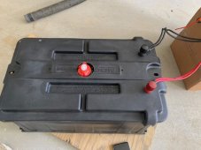
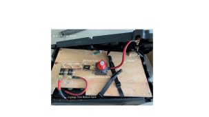
Batteries arranged in a 8S 2P configuration. Built a frame for each bank with tension rods. Banks placed stacked (with a 1/2" gap) in a battery box ("box.jpg" and "batt.jpg")
2 8s Overkill BMSs used (one BMS per 8s)
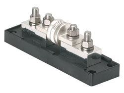
Fuses, wire /buss bar size, and disconnect as shown in photo. (batt.jpg)
All batteries were connected in parallel and top balanced to 3.65v
I did some testing previously with a new hybrid inverter- and noticed one of the cells (cell 6) in the bottom bank of 8, went low and the BMS went into protection. Assuming a loose connection, I took all apart and checked. Nothing appeared loose, and the BMS with no load, indicated equal voltage on all cells. I thought the issue was solved.
Today, I wanted to do a full test to verify If have something close to the advertised 180 Ah the China vendor sold these as.
Ran a 2Kw load for an hour through the inverter (shop vac and space heater - 110v)
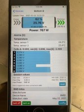
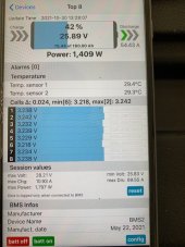
I was periodically checking the BMS app - going back between bluetooth connection to what I call the Top Bank and the Bottom Bank
At some point I notice that the same cell No. 6 was drastically lower than all the others. I also noticed that the amp draw was different on each bank.
See "BottomUnderLoad.jpg", "TopUnderLoad.jpg" for the BMS values when I was pulling a 110v, 2Kw load through the inverter.
I decided to abort the test, and return here to ask questions. See "BottomUnderLoad.jpg" to see the BMS values after the load was turned off. The Cell No. 6 came back to voltage matching all the others.
Questions:
In the 8s 2p setup I have, when under load, should each bank be delivering equal current?
What diagnostic or fix is recommended to determine the problem with Cell no. 6?
After 1 hour of testing, all insulated wires and batteries were only warm, however, my diy copper buss bar (the bar making the parallel connection) was too hot to touch. Is this to be expected given the test load, or a bad design and needs to be fixed? (ref "batt.jpg)
Any other advice before I place the battery in my remote cabin (replacing failing lead acids).
Thank you, John
Batteries: 16 total 180ah Lifeo4. Specifications below
Brand: LiitoKala
Product name: Lithium phosphate iron
Grade: Grade A
Quality: brand new
Material: Aluminum
Rated capacity: 180Ah
Minimum capacity: 160Ah-180Ah
Internal impedance: 0.1~0.5mΩ
Rated voltage: 3.2V
Size: 63*82*277mm (+/-10mm)
Weight: Close to 3.1kg±0.1kg
Recommended current constant: 180A (1C)
Discharge termination voltage: 2.0V
Recommended constant current: 180A(1C)
Charging voltage: 3.65V
Life cycle (90% DOD): 6000
Charging temperature: -5~60°C
Discharge temperature: -30~60°C
Batteries arranged in a 8S 2P configuration. Built a frame for each bank with tension rods. Banks placed stacked (with a 1/2" gap) in a battery box ("box.jpg" and "batt.jpg")
2 8s Overkill BMSs used (one BMS per 8s)
Fuses, wire /buss bar size, and disconnect as shown in photo. (batt.jpg)
All batteries were connected in parallel and top balanced to 3.65v
I did some testing previously with a new hybrid inverter- and noticed one of the cells (cell 6) in the bottom bank of 8, went low and the BMS went into protection. Assuming a loose connection, I took all apart and checked. Nothing appeared loose, and the BMS with no load, indicated equal voltage on all cells. I thought the issue was solved.
Today, I wanted to do a full test to verify If have something close to the advertised 180 Ah the China vendor sold these as.
Ran a 2Kw load for an hour through the inverter (shop vac and space heater - 110v)
I was periodically checking the BMS app - going back between bluetooth connection to what I call the Top Bank and the Bottom Bank
At some point I notice that the same cell No. 6 was drastically lower than all the others. I also noticed that the amp draw was different on each bank.
See "BottomUnderLoad.jpg", "TopUnderLoad.jpg" for the BMS values when I was pulling a 110v, 2Kw load through the inverter.
I decided to abort the test, and return here to ask questions. See "BottomUnderLoad.jpg" to see the BMS values after the load was turned off. The Cell No. 6 came back to voltage matching all the others.
Questions:
In the 8s 2p setup I have, when under load, should each bank be delivering equal current?
What diagnostic or fix is recommended to determine the problem with Cell no. 6?
After 1 hour of testing, all insulated wires and batteries were only warm, however, my diy copper buss bar (the bar making the parallel connection) was too hot to touch. Is this to be expected given the test load, or a bad design and needs to be fixed? (ref "batt.jpg)
Any other advice before I place the battery in my remote cabin (replacing failing lead acids).
Thank you, John