diy solar

diy solar

Tiny BMS controlling 105Ah 12v pack

Pierre

Somewhere down South
Joined
Dec 21, 2019
Messages
1,147
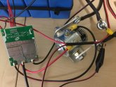
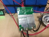
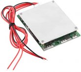
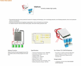
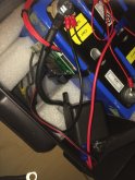
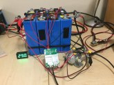
a While ago I bought this tiny Split Port 4S BMS on Amazon for about $10 . Rated at 100 amp , so I was not convinced. It arrived in a little brown box without any label , spec sheet or user manual. Obviously some kind of bypass relay had to be used to handle the current , so I hooked it up to a automotive 12v Cole Hersee 85 amp relay. Unfortunately, as Steve said, these relays are power hungry and this one requires 750mA to energize and it gets quite warm to the touch. I would like to replace it with a SSR and waiting for Steve & Co to come up with a cost effective unit.

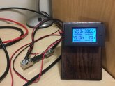
The present setup for testing is as follows : Victron 230v 1200W inverter , Victron 12v 10/20 amp charger , charging at 10 amps and load drawing about 38 amps ( as shown on the Drok ) and resultant current out of the battery is 28 amps ( as shown on the Hall effect meter ). I am monitoring the cells V as it charges and cells delta is 8mV. Will post further result as tests progress. Also looking on the wide web for further info on this BMS.
It shows that you do not need an expensive BMS to control things. Tiny BMS 4.JPGTiny BMS 4.JPGTiny BMS 3.JPGTiny BMS 2.JPGTiny BMS 1.JPG
 
After a few days of testing I found the following :
(1) To latch the bypass relay a pulse is required from P- to B- on first switch-on.
(2) When a charger is connected to C- , charging (at 10 amps) is switched off when the Vpack reaches 13,8v . During the charge cycle the cells delta V
was within 20mV but I think it was because the cells were well matched by now and its not a function of the BMS in this instance.
(3) When the charger is connected to the charging port P- , no protection is present for Pack O/V. At 14,9v the BMS still allowed charging.
Not to be used without some other means of protection.
(4) No Pack U/V detection is present. At 10,7v the pack was still discharging. Other means of protection is required.
(5) The bypass relay gets quite hot from coil heat dissipation and not load current. Suggest using an SSR.
Conclusion : As a cheap device it can be used with additional precautions.

This concludes my testing of the Tiny BMS.
 
(3) When the charger is connected to the charging port P- , no protection is present for Pack O/V. At 14,9v the BMS still allowed charging.
I don't understand. You purposely connect the charger to the port that is NOT for charging and you are surprised it does not protect overcharging?

(4) No Pack U/V detection is present. At 10,7v the pack was still discharging. Other means of protection is required.
What are the U/V specs for this unit? Many that I have seen cutoff when individual
cells fall below 2.5v. Having the entire battery .7v above that could be operating "as designed".

Do you have a link to the product on Amazon? I have a bunch of small batteries and would like a cheap and cheerful BMS for them.
 
I don't understand. You purposely connect the charger to the port that is NOT for charging and you are surprised it does not protect overcharging?


What are the U/V specs for this unit? Many that I have seen cutoff when individual
cells fall below 2.5v. Having the entire battery .7v above that could be operating "as designed".

Do you have a link to the product on Amazon? I have a bunch of small batteries and would like a cheap and cheerful BMS for them.
Sorry MS , I made a hash of this. First time I experimented with split port BMS. Got port numbers confused. Will re-do observations.:mad:
I have no specs on this BMS as it came without any docs.
I tried to search the product on Amazon but will have to go back to my records. The product code is on the PC board.
I will discharge pack again to below 10v and confirm.
 
Last edited:
After a few days of testing I found the following :
(1) To latch the bypass relay a pulse is required from P- to B- on first switch-on.
(2) When a charger is connected to C- , charging (at 10 amps) is switched off when the Vpack reaches 13,8v . During the charge cycle the cells delta V
was within 20mV but I think it was because the cells were well matched by now and its not a function of the BMS in this instance.
(3) When the charger is connected to the charging port P- , no protection is present for Pack O/V. At 14,9v the BMS still allowed charging.
Not to be used without some other means of protection.
(4) No Pack U/V detection is present. At 10,7v the pack was still discharging. Other means of protection is required.
(5) The bypass relay gets quite hot from coil heat dissipation and not load current. Suggest using an SSR.
Conclusion : As a cheap device it can be used with additional precautions.

This concludes my testing of the Tiny BMS.
PLEASE IGNORE THE ABOVE COMMENTS -- WILL REDO ONCE I HAVE CORRECTED MY MISTAKES !! :mad:
 
Corrected observations of the performance of the 'Tiny' BMS :
MisterSandals called me out above (rightly so) about incorrect connections etc. Let me explain where the confusion arose - The Single Port DGJBD 4S BMS I reviewed in another thread came with the leads marked B- and C- , but the Single Port Daly 4S that I started off with came with the leads marked B- and P-.
Since I worked with the DGJBD immediately before the new 'Tiny' 4S Dual Port , I assumed that the additional P- was the charging port.
I have now tested the unit , correctly connected , over the last two days. My findings are as follows :

(1) To latch the bypass relay, a pulse is required from P- to B- on first switch-on or the charger input must be active i.e. charger connected and charging.
(2) Charger connected to C- port and charging at 10 amps (max permissible) : BMS turned charging off when the Vpack was 14,08v and the highest Vcell was 3,65v , so overcharge protection is present.
(3) Load (38 amps) connected through bypass relay and BMS deactivated the relay coil at 10,2Vpack and lowest 2,0Vcell , so over discharge protection is present.
(4) The bypass relay gets quite hot from coil heat dissipation and not load current. Suggest using an SSR. That will be my next experiment.
(5) I did not confirm the cell balancing (30mA) as my pack cells are very closely matched between 10/90% SOC and at 30mA it will take forever to try and balance outside of these limits.
(6) I did not test over current protection as one can fuse the P- connection to the relay coil at 2amps and the main load as required and I did not want to burn up the BMS.

Conclusion : As a really affordable device it works great but I will be hesitant to control more that 20 amps without a bypass device. I will buy another one - love it !
The unit is available on Amazon : Search for Walfront 4S BMSTiny 4S BMS.jpgTiny BMS Specs 1.pngTiny BMS Specs 2.png
 
Last edited:
Just an FYI: TinyBMS is actually a brand of BMS hence why I looked at this thread because you said "tiny bms" in the name.
TinyBMS is a seriously nice product but NOT cheap either when you add it all up.
REF: https://www.energusps.com/shop/category/battery-management-4

RELAY Tests... Yes SSR's are nice but MOST are not up to real DC Loads like we use. The first give away is the small screws ! How do you attach 1/0 or 4/0 cables to that ? I use 4/0 Cable for my DC Power Lines. I received my new 500A SSRS and they come with 1/2" lugs and large pads to handle the power. The relays will handle 72VDC @ 500A and the contactor works from 3-32vdc.
500A solid state relay is 78 usd ea + The heat sink is 4.8 usd ea + Shipping

DONGYA Energy Saver (MUST SPECIFY ENERGY SAVER) approximately $30 USD + S&H
Model: DH200A (High voltage DC contactor) *
Rated Current: 200A
Main contact N.O. (stud type)
Coil Voltage: 9V - 36V
The length of coil leads: 390mm
Terminal type: No
Install method: Horizontal
* = not to be confused with DH200H. The DH200A is the energy saver model. I made that mistake at first, now costing me $$ because I have to get the A series ones, not the H series that I had ordered not realizing the difference when looking at the data. (my bad, I missed it)
Thanks for the heads-up Steve re the TinyBMS. I have come across it and I am sure that they will let me get away with using the adjective.
I am also grateful for the sources of relays you posted -- I have looked at hundreds of SSR's on Amazon but they all look dodgy with tiny ;)contacts. I am watching your progress with these SSR's with great interest and will rather not waste money on a cheapy at this time.
I can get some good quality ones rated at 100 amps from RS Components here in ZA but they are around US$ 100.00
I will rather purchase one that you approve of in the future.
 
BMS deactivated the relay coil at 10,2Vpack and lowest 2,0Vcell , so over discharge protection is present.
I was pretty interested until i saw the 2v low cell cutoff. My understanding is that below 2.5v is where serious damage occurs.

That was a good test and writeup.
 
How I love using this bypass relay - at 68 amps the Vdiff across the contacts is 50mV ! Now I must just source one with lower coil current and therefor less room heating ability ! This darn thing gets hot :mad: . Looking at one of those used Kilovacs for now.
 
A Bad News UPDATE ?

I received the two 500A Big Lug SSRS - They are UNI-Directional ! (aka polarised).
The two Dongya DH200H Relays turned out to be Uni-Directional and NON-Energy Savers. They should have been the DH200A series which are Energy Saver's but they are not Bi-Directional. either, I am now waiting on an update from them as to which model is Bi-Directional.
The Uni-Directional Relay / Contactors are NO use for a Common Port Configuration.

I wrote up a two page document with images of typical configurations and methods used for Energy Storage Systems with Relays, additionally, I added further information in regards to possibly getting a Relay with a 2 channel opto-coupler type of interface. The ability to use ONE Relay / Contactor but accept two Relay Signals and disconnect if either drops could solve many an issue for a number of folks. That info has now been sent to the two manufacturers and hopefully, I will hear back soon. So now I have a pile of relays at serious expense (and wasted time waiting for them) and no further ahead....

Never know, maybe the companies can come up with something 'interesting' at a reasonable price point.
Thanks very much for all your updates @Steve_S -- much appreciated and following with great interest. Just found an automotive relay contactor locally that can switch 300 amp surge and 130 amp continuous , 4w coil energy for about US$50 - not bad for now.
 
The cheap bypass relays I ordered from the US will be here in a few days -- cannot wait to test them ( rated at 130 amp continuous ) to see if they are going to melt ! Will post update soon.
 
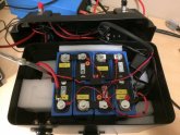
Finally received bypass relays and this test setup has morphed into a portable camping battery pack capable of delivering 1580Wh of energy.
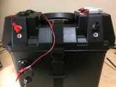
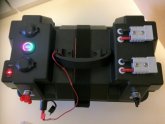
I tested the bypass relay at 65 amps and after about 30 min it was only slightly above room temp. The charging port on the small BMS is limited to only 10 amps so I reconfigured one of the Brad Harrison connectors as an input / output fused at 50 amps but still running through the bypass relay contact. The BMS controls normal functions like cell monitoring , pack UV / OV but not an over current situation. This is protected by an 80 amp fuse in the + line close to the battery. Also incorporated is a 120 amp manual isolator close to the + terminal and mounted on the front of the battery case for a quick disconnect in case of problems and when the pack is not in use. Charging at home is via a Victron Blue Smart Charger 12v/20A and while camping will be charged from 240 watt solar via a Victron Smart Solar 100/30 MPPT controller. On top of the case are 2 x USB ports , 1 x cigarette socket , 2 x Brad Harrison connectors and a digital voltage indicator. I still need to neaten up the packaging around the cells and have attached a few photos of the layout. Camping Pack 4.JPGCamping Pack 3.JPGCamping Pack 2.JPGCamping Pack 1.JPG
 
Must say I am very satisfied with this portable power pack. I use it in the house to charge phones , iPad and power banks and testing stuff in the workshop.
In the RV I use it for the same and also to run the 230v / propane fridge , while towing , via an old 800w modified sinewave inverter which I found abandoned amongst my stuff. Whilst camping it is great for all kinds of applications as well.
 

diy solar

diy solar
Back
Top