diy solar

diy solar

Trace SW5548 miss reading battery voltage.

Jake59

New Member
Joined
Feb 10, 2022
Messages
29
Location
The PNW
I have had a Trace Engineering SW5548 installed at our off grid cabin and running continuously since first installed in 2004 so 18 years, no complaints about that.
However this morning I find no power on and when I investigate the inverter has shut down when I reset she runs momentarily and then shuts down again. What I am able to find out is the unit is monitoring the batteries at 10+ volts higher then actual. Meaning I get 51vdc with my Fluke meter but the inverter is showing 67-70vdc.
This is out of the blue, I have never had any issues with this unit before now, so I am thinking it might be a simple fix.
Couple of questions do these units have an internal battery for the circuit boards to hold the programming?
Is there a trim adjustment for this voltage valve?
Is there a electrical schematic anywhere to be found?
This thing is a tank (heavy!) so if I need to remove it to service, I would like to have a plan so l’m not moving it more then I have to.
Thanks in advance for any help.
SW5548 retains no user settings if battery power lost. (SW5548plus does)

SW5548 does not have backup battery.

There are trim pots for adjustments but there are a lot of them. Adjusting the wrong one can have significant issues, like phase matching calibration.

I have been trying to get a full schematic for over twenty years. Even tried to bribe an authorized service tech to allow me to make a copy of his service CD. Xantrex put the fear of god into them for disclosing info.

If you have battery temp sensor plugged in, first thing I would do is disconnect it to see if it effects battery voltage reading.

Only other suggestion is to lightly tap on trim pots to see if one causes battery voltage to jump. The tapping could also cause other pots to get mis-adjusted, however.
 
Last edited:
If you have temp sensor plugged in, first thing I would do is disconnect it to see if it effects battery voltage reading.

It's been a while but I recall this being a temp sensor issue and that it do with a main board which required me to send the entire inverter in for repair. My most noticeable issue was that fan was running when it shouldn't.

If RCinFLA can't get you straightened out it looks like the Inverter Service Center is still around. Once upon a time they could fix SW series inverters.
 
Well now with this information, I shut everything down for an hour and restarted.
Cooling fan came on (why? ambient temperatures are low 60’s) voltage dropped to 55-56 vdc as soon as the fan kicked off the voltage jumps to 71 vdc. Note I have checked between the actual and temperature compensated voltage and it has been consistently 1-2 volts of each other.
So I just now I have disconnected the battery temperature sensor and all voltages returned to normal 52 vdc matching my fluke meter readings just now both comp and actual voltages are identical as one would expect.
 
Thermistors have a common habit of going bad over time.

From what you are describing it sounds like a ribbon cable grounding connection problem between fan ground and battery temp sensor ground return.

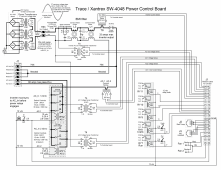
The common denominator here is they both come through the AC terminal/relay board through a 24pin ribbon cable to processor controller main board. If you are digging in, you might unplug ribbon cable from J1 socket on power control board and re-plug it back in.

One word of warning. If you ever totally remove the relay power control board, mark the two wires from the power transformers on TB3 connection. They are not color coded and if you reassemble board with these two transformer wires reversed, the inverter phase sensing will be 180 degs out of phase with AC inputs phase the controller is expecting. As the inverter drives the two into phase lock it will actually drive them 180 degs out of phase lock and inverter will go bang and pop input breaker when connect relay closes. You will then need to change your underwear.
Trace UPS Pwr Board.png
 
Last edited:
Thermistors have a common habit of going bad over time.

From what you are describing it sounds like a ribbon cable grounding connection problem between fan ground and battery temp sensor ground return.

The common denominator here is they both come through the AC terminal/relay board through a 24pin ribbon cable to processor controller main board. If you are digging in, you might unplug ribbon cable from J1 socket on power control board and re-plug it back in.

One word of warning. If you ever totally remove the relay power control board, mark the two wires from the power transformers on TB3 connection. They are not color coded and if you reassemble board with these two transformer wires reversed, the inverter phase sensing will be 180 degs out of phase with AC inputs phase the controller is expecting. As the inverter drives the two into phase lock it will actually drive them 180 degs out of phase lock and inverter will go bang and pop input breaker when connect relay closes. You will then need to change your underwear.
View attachment 115594
Thanks this was exactly the kind of help I was hoping for. With the mounted location in our cabin and its weight, I might not be getting to this for awhile so I am going to cut and paste your response into my off grid note book.
Again thanks.
 

diy solar

diy solar
Back
Top