diy solar

diy solar

Trying to find a BMS to fit my setup

Bleedingblue

Solar Enthusiast
Joined
May 12, 2020
Messages
564
Recently purchased 48-280AH cells. Going to run them in a 48 volt system.

I've emailed several BMS manufacturers and only a couple got back with me saying they do not make a BMS for a 48 volt system or I'd have to buy a certain battery they supply BMS for.

I've asked several people including the company I bought my cells from how I should run these cells. 3 strings of 16cells for a 280 string, or have 3 cells in parallel and run those 16 in a big battery bank for a 840AH single bank. The company I bought them from said to run 3 strings. One of the BMS manufacturers that did not make a 48 volt BMS said to run in a single 840AH bank. Another who does not make a 48 volt BMS said not to run 1 bank.
The seller said to use a Daly or Ant BMS but no specific BMS by them to use. That is like asking what vehicle do I need to buy for a trip and the person comes back with Ford or Chevy. Maybe a I need to pull a camper up in the Mountains? Maybe I need something that needs good mileage or something that seats a lot of people. No specifics whatsoever about the BMS I need to buy.
So really no clue what I should do. If a cell goes bad then the whole bank goes down.
How can a BMS handle that much power surging through it in a 840AH bank?
How in the world do you hook up 4/0 cable in a BMS?
I'd like my BMS to communicate with the hybrid charge controller with a canbus.
Like the BMS to be dependable.
I don't want to baby sit the BMS.
I will not have internet to the BMS.
How many amps will the BMS need to have if I'm running a house and shop off it?
Why does current flow through a BMS if all it needs to do is balance the cells?
May need a low temp disconnect but plan on building an insulated enclosure for it with heating mat.
What level of cell monitoring do I need? I just want it to work and for me not to worry about it.
So do I need 1 BMS or 3? Connect those 3 in parallel somehow?
In the future I may expand my battery setup even more.


I've seen videos of Will messing around with a 48 volt BMS and it had 12 guage wires. Their is no freaking way that 12 guage wires would be able to handle the amount of current that is going to be needed supplying a house and shop. I'd be ashamed to manufacturer a BMS that only had such tiny wires.

Most of the videos I've seen where people are using a BMS they are confused by them and takes them forever to try and set it up.
 
Got this email from the company im looking at purchasing several hybrid charge controller/inverters from.


If your inverter is paralleled, all inverters need to share a battery pack. 16PCS* 3 strings in parallel is a good choice, each string needs a BMS 150A. For other questions, you can ask your battery supplier, who will give more professional answers.


Anyone have a schematic on how that should be?
 
If I'm reading their response right, as long as all three strings come into a single busbar that then feeds the inverters, that should be good enough.
 
How can a BMS handle that much power surging through it in a 840AH bank?

You have three seperate 48V 'batteries', each 16 cells. Parallel them together. Afterwards, each bank can e.g. supply 150A (assuming a 150A BMS), for a total of 450A, or 21.6kW.

How in the world do you hook up 4/0 cable in a BMS?

You don't. You use a bus bar and connect them to that. The three BMS's connect to the bus bar with whatever wire they need to handle their individual load.

How many amps will the BMS need to have if I'm running a house and shop off it?

Entirely depends on your consumption. You can get a 300A BMS, or one that drives relays for even higher currents.

Why does current flow through a BMS if all it needs to do is balance the cells?

Because in a FET based BMS, that's how it can disconnect the charger/load in case of an error (temperature, voltage, etc.). You can use a relay based one and then it doesn't need to - the relay does.
 
Welcome to the forum.

Regarding setup. I have to say, the 280AH cells ate 5.2Kg EACH / 11 Lbs ! These buggers are HEAVY and put 16 together, you will need help shifting it all around. 48VDC pack requires 16 LFP cells 88Kg / 194 Lbs. I highly recommend applying KISS rules to your build. Stick with 3 Packs of 16-Cells configured in Parallel which will accommodate Load & Charge sharing in a Common-Port BMS Configuration. This is an excellent guide from Victron which is really a GOTO in proper battery bank design: https://www.victronenergy.com/upload/documents/Wiring-Unlimited-EN.pdf

BMS': Well this is the tricksy area may trip on. There are MANY types of BMS' out there. The variety of functions, Capabilities and Methods they use makes it more confusing because there are so many ways they can be used relative to the application. Be they Electric Vehicles, to Energy Storage Systems to active / passive systems and so on. I myself am an Offgridder living on Solar Power only, my packs (4 LFP Packs) use Chargery BMS' with external Contactors (no voltage issues there), it's all about the contactor relays handling the amperage going through them. Typically MosFET based BMS' cap at 250A because heat management - dissipation and quite often they are Voltage Constrained as well. As well with MosFET based BMS', you never want to take them to the "edge" of their capacity, it's generally best to have a 25% margin, so if you know you will have max of 100A then you want a BMS capable of at least 125A, more is better to prevent reaching the edge limit.

The Amp Hours a battery bank holds is not related to the Amperage that can be pulled from it, just for how long you can pull X Amps from it. A BMS cares not for the amount of Amp Hours / Killowatt Hours aside from capacity & state of Charge / Discharge the battery packs are at. A 280AH cell can output 280Amps (1C Discharge rate). A 48VDC/280AH pack can still only output a maximum of 1C (280Amps).

! MOST IMPORTANT !
Before launching yourself on a shopping spree, do the math, workout the amperage your going to pull on the AC side. Then work out the sizing of the Inverter to be able to handle your loads, Have a PLAN because without a plan, you plan to fail and or et really costly very quickly.

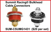
My own system uses Royal Excelene 4/0 Fine Welding Cable. These cables are Very Fine Pure Copper and have more strands than most other brands, while not cheap, you really do get what you pay for. REF: http://industrial.southwire.com/en/search_products/?search_field=excelene I use a combination of 3/8 & 5/16 Tinned Lugs as appropriate, I like the tinned ones from https://selterm.com/pages/battery-cable-lugs which are very high quality. Because I use a Chargery BMS with external relay controls, the wires are NOT connected to the BMS as such but the Relay Contactors instead, the relays handle the "juice" as it were. Connecting the wires to the Cell's, I used 5/16 LUGS on the Cell Side (they are M8 bolts so 5/16 is best fit) which go to 3/8 Case Terminals (on the battery box) and then 3/8 with 4/0 wires to relays & shunt.

Best Bang per Buck on Case Terminals from Summit Racing
sum-csumg1431_xl.jpg

CANBUS: Ok, that protocol is not supported by all devices. Some BMS' do have CanBus, some have ModBus and others like the Chargery only has RS232 output. There are ways to have an intermediary with something like a Raspberry Pi which reads in the RS323 signals and processes them and takes actions based on the inputs. That is a whole other story altogether. Luckily one of our people here has started a thread with lots of goodies on all of this.
Check out this thread on it: https://diysolarforum.com/threads/o...itoring-and-control-freeware.6662/#post-69963

How many amps will the BMS need to have if I'm running a house and shop off it?
The BMS has little to do with this. The BMS is a MANAGER, which will cut off the battery at Low Voltage, Over Voltage, or if Temps are out spec. NOT ALL BMS, have Cold Temp Cutoff ! Many will have Balancing functions but not all do. Chargery does all of this BTW.

You have to determine what YOUR loads are and you should size your Inverter to handle said load requirements. As I said, I am offgrid/solar running with 24VDC Battery Bank set for a max of 200A which provides me with 4800 Watts (although my inverter is capable of burst to 12,000W or 500A). You have to look at the amount of Amps your AC system will pull and then right size the inverter to be able to deliver the required amperage. 240V@100A = 24,000 Watts. 24,000W ÷ 48VDC = 500A.

I think I covered the majority of your points.
I hope it helps, Good Luck
Steve
 
Was going to reply to some of your many specific questions (probably still will) but Instead I'm going to make a general observation/recommendation.

If you are building your own 48 cell, 48 Volt, whole home battery bank, you are deep into DIY / 'teach a man (teach yourself) to fish' territory. Being this far out in the DIY wilderness, its on us (unless we outsource the design work to a professional) to spend the time to learn what we need to learn to design our systems and to know what we need. It can be a bit daunting, and overwhelming at times (and BMS' are definitely one of the more confusing and esoteric pieces of the puzzle), but there really is no substitute in my opinion to putting in the time and mental legwork (starting with the fundamentals of electricity and system design). There is a somewhat steep learning curve, and not a ton of beginner friendly learning resources, but you are capable of it!

That is like asking what vehicle do I need to buy for a trip and the person comes back with Ford or Chevy. Maybe a I need to pull a camper up in the Mountains? Maybe I need something that needs good mileage or something that seats a lot of people. No specifics whatsoever about the BMS I need to buy.


This is a two way street--setting aside the fact that these sellers are generally not used to or prepared for the type of handholding and guidance more typical of mainstream consumer facing retail sales--in order to get a specific answer you need to give specific details about your application, your needs, your system design, and priorities, and you need to have some idea what you want and need. Using your vehicle analogy, if you went to a dealer asking only 'what vehicle do i need for a trip' not only could the dealer not narrow it down beyond Ford and Chevy, they couldn't even narrow it down to a car, they could reasonably recommend a motorcycle, or even bicycle or boat, without knowing more details about your needs and goals and parameters.


My broad point, is that I think it would be helpful if you take a few steps back, learn the basics, define your needs (in more detail than enough to "power a house and shop") and try to understand what a BMS is conceptually, what it accomplishes, the basics of the different types, and how it will fit into your system. Then circle back to the specifics. I'm new to this too, and I've found it helpful to focus on understanding what a BMS does, more than what it is.


If you can define and learn these things, a lot of your specific questions will answer themselves, and you will be much more empowered to know what you need, and to then ask specific questions, and go to BMS sellers armed with the details you need to (1) make a semi-informed decision and feel semi-confident about it, and (2) ask questions that they are actually able to answer.
 
I've asked several people including the company I bought my cells from how I should run these cells. 3 strings of 16cells for a 280 string, or have 3 cells in parallel and run those 16 in a big battery bank for a 840AH single bank. The company I bought them from said to run 3 strings. One of the BMS manufacturers that did not make a 48 volt BMS said to run in a single 840AH bank. Another who does not make a 48 volt BMS said not to run 1 bank.

One reason you are not getting a straight answer on this point, is that there is no clear consensus here. Both options (16s3p or 3p16s) are acceptable and both have their pros and cons.

How can a BMS handle that much power surging through it in a 840AH bank?

Just to clarify, and forgive me if you already know this, Amp hours (in this context) are a measure of stored energy not power (Watts) or current (Amps). Your battery banks capacity is irrelevant to the current rating of the BMS.

Why does current flow through a BMS if all it needs to do is balance the cells?

This is both an insightful and misguided question.

It is misguided because balancing is not the only thing (or even the most important thing) that a BMS does. A BMS is in charge of battery management, protection, and monitoring. This can mean a lot of things, two of the most common and most important aspects of this are under and over voltage protection (often abbreviated as LVD and HVD). To do this the BMS needs to either be in the current path or control something (such as high current relays) which is in the current path.

It is an insightful question, because you correctly guessed that the BMS does not actually have to be in the current path, and many/most high current and/or high end BMS' are not directly in the current path (See SBMS0 and Chargery BMS for examples).

For a system your size/cost, I would be looking into high end, high current options, they are prohibitively expensive for small systems, but for a whole home system I think the cost can be justified. I don't have the experience or knowledge to recommend one but Batrium, 123 Smart BMS, and REC BMS might be decent places to start your research. Chargery would be a more affordable high current option.

How many amps will the BMS need to have if I'm running a house and shop off it?

At least as much current as required to run your house and shop. Only you can know or estimate what that might be. In the resources section of this website, there is a useful spreadsheet for calculating this.

How in the world do you hook up 4/0 cable in a BMS?

If you need 4/0, its highly unlikely you will be using an inline BMS.

I'd like my BMS to communicate with the hybrid charge controller with a canbus.

Some budget commodity BMS' have canbus as an option (can't recall specifics off the top of my head), but I think might consider some coding and customization to make use of (someone correct me if I'm wrong on this point).

Its a more common feature (and I think easier to integrate with other system components--particularly Victron) with some of the higher end BMS' (I believe REC BMS and 123 Smart BMS advertise compatibility with Victron)

May need a low temp disconnect but plan on building an insulated enclosure for it with heating mat.

Sounds like you don't need it then, but if it were me, I would want the redundancy and peace of mind of having it, with a bank this size.

What level of cell monitoring do I need? I just want it to work and for me not to worry about it.

The absolute minimum in my opinion should be:
  1. Cell level monitoring
  2. Cell level undervoltage protection
  3. Cell level overvoltage protection
  4. Cell Balancing
State of charge ('battery fuel gauge') monitoring, is not 100% necessary, but is very nice to have. The BMS doesn't have to be the component that accomplishes SOC monitoring but its one logical place to do so.

So do I need 1 BMS or 3? Connect those 3 in parallel somehow?

I don't have a full deep understanding of the trade-offs, but the high level explanation is
1 BMS = Simpler, cheaper, less connections and components to potentially fail, 1 logical battery pack
3 BMS = True cell level monitoring, redundancy, 3 logical battery packs
 
Last edited:
I understand i need a 16s because im running 16 cells in a string but which ones can handle the load?

What does your load look like? As in, if you need 20kW, and you have 3 parallel batteries, each BMS needs to drive 'something' that can handle ~150A or so at 48V. This 'something' can be a relay or a bunch of FETs.
 
Which ones that will hold the amps i need?

Just to clarify (again sorry if you already understand this and I misunderstood you), amps are a measure of 'flow rate' or electrical current, similar to water flowing through a pipe.

The relevance in understanding this is that, amps are not held, and BMS rating is not relevant to how many amp hours your battery bank stores, as @upnorthandpersonal said above, its your total loads that is important. I.E. how much current will pass through the BMS (or the contactors the BMS controls) at a given time. And not recommendations you receive here can be accurate without knowing what your loads will be.

I found this video very helpful when learning the fundamentals of electricity and the nature of the units we use. It is a very good conceptual video for the non-electrical professional / non-engineer

 
Last edited:
Welcome to the forum.

Regarding setup. I have to say, the 280AH cells ate 5.2Kg EACH / 11 Lbs ! These buggers are HEAVY and put 16 together, you will need help shifting it all around. 48VDC pack requires 16 LFP cells 88Kg / 194 Lbs. I highly recommend applying KISS rules to your build. Stick with 3 Packs of 16-Cells configured in Parallel which will accommodate Load & Charge sharing in a Common-Port BMS Configuration. This is an excellent guide from Victron which is really a GOTO in proper battery bank design: https://www.victronenergy.com/upload/documents/Wiring-Unlimited-EN.pdf

BMS': Well this is the tricksy area may trip on. There are MANY types of BMS' out there. The variety of functions, Capabilities and Methods they use makes it more confusing because there are so many ways they can be used relative to the application. Be they Electric Vehicles, to Energy Storage Systems to active / passive systems and so on. I myself am an Offgridder living on Solar Power only, my packs (4 LFP Packs) use Chargery BMS' with external Contactors (no voltage issues there), it's all about the contactor relays handling the amperage going through them. Typically MosFET based BMS' cap at 250A because heat management - dissipation and quite often they are Voltage Constrained as well. As well with MosFET based BMS', you never want to take them to the "edge" of their capacity, it's generally best to have a 25% margin, so if you know you will have max of 100A then you want a BMS capable of at least 125A, more is better to prevent reaching the edge limit.

The Amp Hours a battery bank holds is not related to the Amperage that can be pulled from it, just for how long you can pull X Amps from it. A BMS cares not for the amount of Amp Hours / Killowatt Hours aside from capacity & state of Charge / Discharge the battery packs are at. A 280AH cell can output 280Amps (1C Discharge rate). A 48VDC/280AH pack can still only output a maximum of 1C (280Amps).

! MOST IMPORTANT !
Before launching yourself on a shopping spree, do the math, workout the amperage your going to pull on the AC side. Then work out the sizing of the Inverter to be able to handle your loads, Have a PLAN because without a plan, you plan to fail and or et really costly very quickly.

My own system uses Royal Excelene 4/0 Fine Welding Cable. These cables are Very Fine Pure Copper and have more strands than most other brands, while not cheap, you really do get what you pay for. REF: http://industrial.southwire.com/en/search_products/?search_field=excelene I use a combination of 3/8 & 5/16 Tinned Lugs as appropriate, I like the tinned ones from https://selterm.com/pages/battery-cable-lugs which are very high quality. Because I use a Chargery BMS with external relay controls, the wires are NOT connected to the BMS as such but the Relay Contactors instead, the relays handle the "juice" as it were. Connecting the wires to the Cell's, I used 5/16 LUGS on the Cell Side (they are M8 bolts so 5/16 is best fit) which go to 3/8 Case Terminals (on the battery box) and then 3/8 with 4/0 wires to relays & shunt.

Best Bang per Buck on Case Terminals from Summit Racing
View attachment 16444

CANBUS: Ok, that protocol is not supported by all devices. Some BMS' do have CanBus, some have ModBus and others like the Chargery only has RS232 output. There are ways to have an intermediary with something like a Raspberry Pi which reads in the RS323 signals and processes them and takes actions based on the inputs. That is a whole other story altogether. Luckily one of our people here has started a thread with lots of goodies on all of this.
Check out this thread on it: https://diysolarforum.com/threads/o...itoring-and-control-freeware.6662/#post-69963

How many amps will the BMS need to have if I'm running a house and shop off it?
The BMS has little to do with this. The BMS is a MANAGER, which will cut off the battery at Low Voltage, Over Voltage, or if Temps are out spec. NOT ALL BMS, have Cold Temp Cutoff ! Many will have Balancing functions but not all do. Chargery does all of this BTW.

You have to determine what YOUR loads are and you should size your Inverter to handle said load requirements. As I said, I am offgrid/solar running with 24VDC Battery Bank set for a max of 200A which provides me with 4800 Watts (although my inverter is capable of burst to 12,000W or 500A). You have to look at the amount of Amps your AC system will pull and then right size the inverter to be able to deliver the required amperage. 240V@100A = 24,000 Watts. 24,000W ÷ 48VDC = 500A.

I think I covered the majority of your points.
I hope it helps, Good Luck
Steve


My house has a 4.5 ton air conditioner as does my shop. I also have a welder, plasma cutter which both are around 200 amps. I also have a well and lights not to mention items in the house i might be running all at once while cooking. Deep fryer, oven, microwave, those 3 alone is 4500 watts.

I could easily be looking at using 10,000 watts or more for an extended period of time.

I like the idea of not using fets in the bms. Seems thats asking for it to burn up.

My inverter is an aims 10k with a 30k peak which im not gonna use anymore. Going the hybrid route. Prob gonna have 4- 5K's maybe even 5.


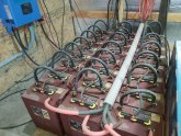
This is my bank i have now. Thats even more weight id like to get rid of.


20200610_141250.jpg
 
What does your load look like? As in, if you need 20kW, and you have 3 parallel batteries, each BMS needs to drive 'something' that can handle ~150A or so at 48V. This 'something' can be a relay or a bunch of FETs.


I think i like the relay idea better than mosfets. If a relay goes bad i can replace it.

But i will be using a good bit of power for extended periods of time. Im thinking easily 12k watts during the day time.
 
Just to clarify, amps are a measure of 'flow rate' or electrical current, similar to water flowing through a pipe.

The relevance in understanding this is that, amps are not held, and BMS rating is not relevant to how many amp hours your battery bank stores, as @upnorthandpersonal said above, its your total loads that is important. I.E. how much current will pass through the BMS (or the contactors the BMS controls) at a given time. And not recommendations you receive here can be accurate without knowing what your loads will be.

I found this video very helpful when learning the fundamentals of electricity and the nature of the units we use. It is a very good conceptual video for the non-electrical professional / non-engineer


Well with those tiny tiny wires coming out of a bms and it will advertise 150 amps thats hard to believe it can handle it. In one of Will Prowse videos it had 12 guage wire.

Im using a 300 amp shunt right now with my 4k setup. Actually produces 3600 watts and i have 3 strings of 370AH batteries. Its getting by fine now with no blown fuses but i also dont have many loads on it. Well, some lights in the house and a couple of fridges and 2 freezers.

It only has a few hrs of reserve. If it is raining the next day i have to turn the charger on.
 
Well with those tiny tiny wires coming out of a bms and it will advertise 150 amps thats hard to believe it can handle it. In one of Will Prowse videos it had 12 guage wire.

I agree, I would not trust the wires some of these BMS' use to handle the current they claim they can. The "320A" Ant BMS from Will's video here comes to mind. I suspect you could solder additional wires if you really wanted, but I think the fact that these BMS are not being wired for their rating indicates that the rating is likely unrealistic. I wouldn't trust it anywhere near its nominal limit for any period of time.

I think using external relays, or wiring the BMS to directly control the Inverter and chargers (and DC loads if you have any) is a better way to manage larger high current systems.
 
The tiny wires are only for cell balancing.


Yes I understand those wires which look like 24 guage are for the cells in balancing. If you put up a 12 guage wire next to a 4/0 wire it is tiny.

In my pic up above on my batteries I use 4/0. I use 4/0 because I know its going to carry a heck of a lot more current than tiny 12 guage wires.
 
I see you're using the watering system on the Trojan batteries. I have only two Trojan's for my Trailer so I never pursued the watering system.

Does the watering system have a one way valve so allow water into the battery but not let it come back into the lines from the battery? If not, doesn't that mean that the electrolyte in the battery is diluted by the water that is still in the line?
 
Welcome to the forum.

Regarding setup. I have to say, the 280AH cells ate 5.2Kg EACH / 11 Lbs ! These buggers are HEAVY and put 16 together, you will need help shifting it all around. 48VDC pack requires 16 LFP cells 88Kg / 194 Lbs. I highly recommend applying KISS rules to your build. Stick with 3 Packs of 16-Cells configured in Parallel which will accommodate Load & Charge sharing in a Common-Port BMS Configuration. This is an excellent guide from Victron which is really a GOTO in proper battery bank design: https://www.victronenergy.com/upload/documents/Wiring-Unlimited-EN.pdf

BMS': Well this is the tricksy area may trip on. There are MANY types of BMS' out there. The variety of functions, Capabilities and Methods they use makes it more confusing because there are so many ways they can be used relative to the application. Be they Electric Vehicles, to Energy Storage Systems to active / passive systems and so on. I myself am an Offgridder living on Solar Power only, my packs (4 LFP Packs) use Chargery BMS' with external Contactors (no voltage issues there), it's all about the contactor relays handling the amperage going through them. Typically MosFET based BMS' cap at 250A because heat management - dissipation and quite often they are Voltage Constrained as well. As well with MosFET based BMS', you never want to take them to the "edge" of their capacity, it's generally best to have a 25% margin, so if you know you will have max of 100A then you want a BMS capable of at least 125A, more is better to prevent reaching the edge limit.

The Amp Hours a battery bank holds is not related to the Amperage that can be pulled from it, just for how long you can pull X Amps from it. A BMS cares not for the amount of Amp Hours / Killowatt Hours aside from capacity & state of Charge / Discharge the battery packs are at. A 280AH cell can output 280Amps (1C Discharge rate). A 48VDC/280AH pack can still only output a maximum of 1C (280Amps).

! MOST IMPORTANT !
Before launching yourself on a shopping spree, do the math, workout the amperage your going to pull on the AC side. Then work out the sizing of the Inverter to be able to handle your loads, Have a PLAN because without a plan, you plan to fail and or et really costly very quickly.

My own system uses Royal Excelene 4/0 Fine Welding Cable. These cables are Very Fine Pure Copper and have more strands than most other brands, while not cheap, you really do get what you pay for. REF: http://industrial.southwire.com/en/search_products/?search_field=excelene I use a combination of 3/8 & 5/16 Tinned Lugs as appropriate, I like the tinned ones from https://selterm.com/pages/battery-cable-lugs which are very high quality. Because I use a Chargery BMS with external relay controls, the wires are NOT connected to the BMS as such but the Relay Contactors instead, the relays handle the "juice" as it were. Connecting the wires to the Cell's, I used 5/16 LUGS on the Cell Side (they are M8 bolts so 5/16 is best fit) which go to 3/8 Case Terminals (on the battery box) and then 3/8 with 4/0 wires to relays & shunt.

Best Bang per Buck on Case Terminals from Summit Racing
View attachment 16444

CANBUS: Ok, that protocol is not supported by all devices. Some BMS' do have CanBus, some have ModBus and others like the Chargery only has RS232 output. There are ways to have an intermediary with something like a Raspberry Pi which reads in the RS323 signals and processes them and takes actions based on the inputs. That is a whole other story altogether. Luckily one of our people here has started a thread with lots of goodies on all of this.
Check out this thread on it: https://diysolarforum.com/threads/o...itoring-and-control-freeware.6662/#post-69963

How many amps will the BMS need to have if I'm running a house and shop off it?
The BMS has little to do with this. The BMS is a MANAGER, which will cut off the battery at Low Voltage, Over Voltage, or if Temps are out spec. NOT ALL BMS, have Cold Temp Cutoff ! Many will have Balancing functions but not all do. Chargery does all of this BTW.

You have to determine what YOUR loads are and you should size your Inverter to handle said load requirements. As I said, I am offgrid/solar running with 24VDC Battery Bank set for a max of 200A which provides me with 4800 Watts (although my inverter is capable of burst to 12,000W or 500A). You have to look at the amount of Amps your AC system will pull and then right size the inverter to be able to deliver the required amperage. 240V@100A = 24,000 Watts. 24,000W ÷ 48VDC = 500A.

I think I covered the majority of your points.
I hope it helps, Good Luck
Steve


Is this what I'm needing?


The 100 amp is $165 and the 300 amp is $185. Is the relay of bad quality? Did you replace yours with another one?


This is the hybrid inverter/ charge controller I'm more than likely going to buy.


I guess the chargery and this unit will communicate back and forth?
 
I see you're using the watering system on the Trojan batteries. I have only two Trojan's for my Trailer so I never pursued the watering system.

Does the watering system have a one way valve so allow water into the battery but not let it come back into the lines from the battery? If not, doesn't that mean that the electrolyte in the battery is diluted by the water that is still in the line?
It is just a 1 way. I've been using it for 5 years I think. However long I have had the batteries I have been using them. My dad had a 24 volt system and he lost several pairs of shirts and jeans using the can that squishes down on the cells to fill. The acid would squirt out.

This system I have actually came with 3 seperate lines. I just used a couple of T connectors and used only 1 line to fill from the tank. When I first installed it I put 3 gals of water in em. Ever since they only use around a 1/2 gal a month on average.
They have been acting weird the past couple days. Don't know whats going on. Acting like I have a huge load on em and draining them. All the current was out this morning when I got up for work at 4 am. Had the charger on all day and it was sunny. Got home and it was still in Bulk mode I turned the charger off and the batteries where at 48.6. So back on the charger they went.

Your battery is going to outgas all the time and your going to have to add water to em. Have to add distilled water not tap. The acid in the batteries will not be diluted. If you do not put water in em you will burn your batteries up rather quickly. They do not like hot weather either.
 

diy solar

diy solar
Back
Top