


In the attachments, I've drawn out three grounding scenarios to help me understand the ground path for a ground fault.
I want to connect a bonded-neutral inverter to a transfer switch, which will allow me to choose between grid, or inverter for 4 select circuits in my main AC sub panel.
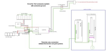
In the first drawing, I have completely isolated the 4 circuits from the grid, except for the connected ground and they can only be run from the inverter. Is this truly "isolated" since the two systems share the ground? It is not my ideal setup, but a fallback in case I am unable to achieve the goal above.
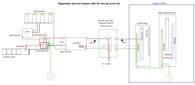
In the second drawing, I am using a transfer switch that isolates all three wires. It also has its own ground rod, as it is a separately derived system.
I believe this shows that the system can safely handle a ground fault through the provided path, and that having a second ground rod 40' away from the AC side ground rod is okay because they are not connected to the same system. Am I mistaken?
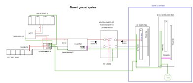
In the third drawing, when I attempt to use a pass through ground in the transfer switch, I end up with neutral bonding in two separate places.
Do you see any errors in my understanding, and or an easier/simpler way to accomplish the goal?
An inverter with a floating neutral would make switching easy, and not require a separate system and ground rod, as I could pass through the ground and neutral, switching only the line, right?
Thank you.
I want to connect a bonded-neutral inverter to a transfer switch, which will allow me to choose between grid, or inverter for 4 select circuits in my main AC sub panel.
In the first drawing, I have completely isolated the 4 circuits from the grid, except for the connected ground and they can only be run from the inverter. Is this truly "isolated" since the two systems share the ground? It is not my ideal setup, but a fallback in case I am unable to achieve the goal above.
In the second drawing, I am using a transfer switch that isolates all three wires. It also has its own ground rod, as it is a separately derived system.
I believe this shows that the system can safely handle a ground fault through the provided path, and that having a second ground rod 40' away from the AC side ground rod is okay because they are not connected to the same system. Am I mistaken?
In the third drawing, when I attempt to use a pass through ground in the transfer switch, I end up with neutral bonding in two separate places.
Do you see any errors in my understanding, and or an easier/simpler way to accomplish the goal?
An inverter with a floating neutral would make switching easy, and not require a separate system and ground rod, as I could pass through the ground and neutral, switching only the line, right?
Thank you.
")