Just to clarify, since I'm going to be doing this soon...you can do it live? as in leave the battery assembled/connected and BMS on and just slap alligator clips on each cell one at a time and top them up? I was thinking that I would have to at least disconnect the battery from the inverter at least before I did it. But does it really matter?Nope. You can do it live.


You are using an out of date browser. It may not display this or other websites correctly.
You should upgrade or use an alternative browser.
You should upgrade or use an alternative browser.
Uneven discharge causing issues
- Thread starter karamazov
- Start date
sunshine_eggo
Happy Breffast!
You must set your power supply for a safe voltage not higher than 3.65V or 0.05V below your BMS cell cutoff voltage before connecting to cell.
Just walk through the pack starting with the lowest cell first.
For an active system, best done when battery is in float.
Just walk through the pack starting with the lowest cell first.
For an active system, best done when battery is in float.
Quattrohead
Solar Wizard
I only have one and it does not match the rest of the JBD BMS I have, therefore it is a pain in the arse to monitor with solar assistant.. actually you can't mix them at all. I have tried other methods but my programming skills are just not up to it.do you have two of them? Also curious as to why you'd want to get rid of them.
TomC4306
Solar Obsessive
He meant yep.Do we do this with the battery pack assembled?
Well...don't think top balance was the problem. I just got done topping up the entire bank and it still has the same problem.
I suspect it is a connection issue but won't be able to take everything apart until next week. I did some quick voltage readings and noticed that the voltage drop from the battery bank 1 positive terminal to the disconnect switch is (apparently) double that of battery bank 2 (they are roughly the same length). It's a tight fit, so I suppose it's possible I took too sharp of a turn with the cable? I suppose there's one way to find out.
I'll report back after I've ripped it apart and redone the connections...
Attachments

TomC4306
Solar Obsessive
3.3 volts per cell is NOT top balanced.Well...don't think top balance was the problem. I just got done topping up the entire bank and it still has the same problem.
I suspect it is a connection issue but won't be able to take everything apart until next week. I did some quick voltage readings and noticed that the voltage drop from the battery bank 1 positive terminal to the disconnect switch is (apparently) double that of battery bank 2 (they are roughly the same length). It's a tight fit, so I suppose it's possible I took too sharp of a turn with the cable? I suppose there's one way to find out.
I'll report back after I've ripped it apart and redone the connections...
Ignore the SOC percentage indicator while top balancing. 100% is above 3.45 volts per cell for a period of time.
Imbalance is only visible above 3.45 volts
And balancing is only effective above 3.45 volts.
Hmm I ran the power supply on each cell for at least 4 hours, the voltage of each cell ended up at around 3.6V, but then dropped back down after I moved on to the next one. Felt like I was playing whack a mole and fighting the passive balancer. Maybe I need to leave them charging for a lot longer. At this point it may be less work to just disassemble the pack and balance them all in parallel.3.3 volts per cell is NOT top balanced.
Ignore the SOC percentage indicator while top balancing. 100% is above 3.45 volts per cell for a period of time.
Imbalance is only visible above 3.45 volts
And balancing is only effective above 3.45 volts.
sunshine_eggo
Happy Breffast!
Hmm I ran the power supply on each cell for at least 4 hours, the voltage of each cell ended up at around 3.6V, but then dropped back down after I moved on to the next one. Felt like I was playing whack a mole and fighting the passive balancer. Maybe I need to leave them charging for a lot longer. At this point it may be less work to just disassemble the pack and balance them all in parallel.
The current in the passive balancer is nothing compared to what the PS can deliver... typically about 0.04A. Balancer should be set to 3.40V, 20mV and disable charge only during balance.
LFP is like lead acid in that it needs elevated voltage to take full charge, then voltage settles after charging.
Charge the entire pack to 56V and see where you are. Voltages only represent balance when above 3.40 and below 3.10
TomC4306
Solar Obsessive
Do what you did but do it while the MPPT is in absorption (constant voltage).Hmm I ran the power supply on each cell for at least 4 hours, the voltage of each cell ended up at around 3.6V, but then dropped back down after I moved on to the next one. Felt like I was playing whack a mole and fighting the passive balancer. Maybe I need to leave them charging for a lot longer. At this point it may be less work to just disassemble the pack and balance them all in parallel.
Set the mppt to 56 volts charging and say 4 hours absorption time. Then, while the mppt is holding the pack at 56 volts, and while you are monitoring the cell voltages in the BMS, apply your light bulb loads to pull down individual cell or apply your power supply to an individual cell to raise it up.
Edit- once you get them all to within 10 millivolts of one another, raise the charge voltage in your mppt to 56.8. rinse and repeat as high as you wish to go.
The higher you go the quicker it goes.
TomC4306
Solar Obsessive
This takes me about 20 minutes per pack every 6 months or so.
Also, when complete, don't forget to put your absorption time back down to 1 hour or whatever suits your fancy.
Also, when complete, don't forget to put your absorption time back down to 1 hour or whatever suits your fancy.
featherlite
Solar Enthusiast
Thanks for the above postings. MUCH appreciated!
I am going to rebalance my packs as soon as this thread matures sufficiently to the point that I am comfortable that I know all that is necessary or helpful to know about the process") .
.
I am going to rebalance my packs as soon as this thread matures sufficiently to the point that I am comfortable that I know all that is necessary or helpful to know about the process
.sunshine_eggo
Happy Breffast!
Thanks for the above postings. MUCH appreciated!
I am going to rebalance my packs as soon as this thread matures sufficiently to the point that I am comfortable that I know all that is necessary or helpful to know about the process
Seriously... charge to 56V and see where the cells land. If all cells are very near 3.50V, then you don't need to top balance again.
Yeah we seem to be missing enough information to tell what is happening.Seriously... charge to 56V and see where the cells land. If all cells are very near 3.50V, then you don't need to top balance again.
Other than the likely, that there is a loose connection.
One tool I have is the ability to measure internal resistance. You don't have to just measure cells with it, you can measure across the entire battery, check connections and any problems pretty easily.
If one battery bank can't provide enough amps by itself then you have a design failure. Every individual battery needs to be able to handle the entire load.
Sounds like you're also lacking the ability to see cell voltages real time
Tonight, I go to bed victorious!
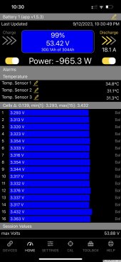
Finally had time to do as @sunshine_eggo and others suggested. Set my inverter to 56V. Charged up cells one by one. I also rebalanced the cells in the other battery as a few looked like they needed it.
Now it looks like some semblance of balance has finally been restored! Both batteries appear to be discharging at *roughly* the same rate now. Going to run a discharge/absorption cycle now and see how they look after that.
A quick root cause analysis for anyone interested (or in the same boat):
- Poor connection on the lead between cells 1 and 2 caused erratic voltage readings on the BMS
- This threw everything out of whack as it was constantly registering cell over/under voltages, and eventually the battery was way out of balance
Solved by a relatively simple albeit tedious rebalance. Thanks to everyone here for the help!
Well…I spoke too soon. Had both BMSs overcurrent last nightTonight, I go to bed victorious!
Finally had time to do as @sunshine_eggo and others suggested. Set my inverter to 56V. Charged up cells one by one. I also rebalanced the cells in the other battery as a few looked like they needed it.
Now it looks like some semblance of balance has finally been restored! Both batteries appear to be discharging at *roughly* the same rate now. Going to run a discharge/absorption cycle now and see how they look after that.
A quick root cause analysis for anyone interested (or in the same boat):
- Poor connection on the lead between cells 1 and 2 caused erratic voltage readings on the BMS
- This threw everything out of whack as it was constantly registering cell over/under voltages, and eventually the battery was way out of balance
Solved by a relatively simple albeit tedious rebalance. Thanks to everyone here for the help!
. At this point I think that there are still probably some bad connections somewhere, but regardless I am going to “do it right” this time. I just ordered 2 JK 200A BMS to replace my overkill solar ones. Just don’t feel like dealing with this issue anymore.
It is interesting how this worked so well for the first 4 months or so of operation.
Similar threads
- Replies
- 4
- Views
- 418
- Replies
- 7
- Views
- 500
- Replies
- 22
- Views
- 1K