diy solar

diy solar

Upgrading panels first, then the battery later, "Over paneling" safely?

venquessa

New Member
Joined
Apr 8, 2023
Messages
219
Location
UK
I have one 330W panel.

I ordered another 2.

My 100Ah battery will not take.... rather, I do not want to throw all 1000W at it.

Similarly I can't increase the load side too much to reduce the amount of "excess solar" going to the battery because the moment the sun goes back in behind the clouds the battery takes a discharge pounding. I'd rather not have to introduce dynamic "bleed loads" either as they are typical just wasting power resistatively.

So I need to current limit the panels. My present MPPT (EPEver 4210AN) does not support current limiting period, except as part of "top of charge tapering". It will supply up to 40A charge current, or 1000W which ever is first.

Solution 1. Just connect all 3 in parallel to the EPEver I have. Let it limit at 40A. It will accept the over-panelling up to 1500W. Accept the higher wear and tear on the battery. Increase the daytime loads and interactively run other loads from teh solar circuit when it's sunny. Micro manage it for a few months.

Solution 2. Same as above, but leave one of the panels disconnected entirely. This will supply 20A or 700W max. Of course this is unsatisfactory as in Ireland the panels spents the majority of its time running nowhere near peak output and so by leaving a panel disconnected I waste 1/3rd of my low light output.

Solution 3. I purchased a Victron MPPT 75/15 Smartsolar. I can connect two panels to it to limit the pair to 15A bringing the total panel current down to 25A. Unfortunately this approach alone only drops 5A off the total and still results in over 30A charge currents.

Solution 4. Hope the additional current limiting features work in the SmartSolar and limit the pair of panels to 10A rather than 15A. This would bring the maximum power point output into managible range and still give me the best low light performance from all 3 panels.

The battery upgrade will depend on whether I wait longer and invest bigger or just duplicate/double up what I have, which I can afford a lot sooner. Even if I choose the later and order them next week, the will not arrive to go into service until August or September. So whatever I do has to be managable until then.
 
Maybe.... I just watch the weather. If it's going to be the normal grey overcast with sunny spells, I can risk leaving all 3 panels engaged in parallel. If it looks like it's going to be a couple of proper sunny days, I can switch one panel off.

EDIT: If I am leaving the house for any prolonged period during the day, switch 2 panels off just in case the weather is unexpectedly sunny.
 
I don't understand the problem. If you set the charge parameters right you shouldn't have an issue with it overcharging. I had to tinker with my 4215bn's settings to get it just right but we are talking wanting it to stay around 80% charge and not make it to 100%. So if I can do that you definitely should be able to keep if from overcharging.

Maybe list your settings out to see if we can make suggestions on how to tune it?
 
My 100Ah battery will not take.... rather, I do not want to throw all 1000W at it
My understanding is the panels do not push power but rather the loads in the system will pull power from the array.
So once the battery is charged the SCC will scale down and only provide what is necessary to power whatever loads you may have running.

The thing to be concerned about is the battery's amp charge limit and the amps the SCC will send to the battery.
That should be an adjustment your SCC can set
Most batteries have a 100a charge limit, some less other's more

The real concern is keeping the total VOC below the SCC's limit, going over releases the SCC's magic smoke.
Over wattage/over paneled is less of a concern because once the SCC hits the wattage limit it clips the production
(note: IMO it's not a good idea to push any component to it's limits for prolonged periods of time so over paneling in good/great sun should be done with some concern)

and example:
I have a Victron smart SCC 100/50, it's wattage limit is 1400w (or so)
I'm over paneled - 2s5p for 2000w @ 50a
Most of the time I rarely see full production from my array (6 panels facing south - 4 panels facing wsw)
On occasion I see my SCC clipping power limiting the amps to 50 while providing the Volts the batteries need for charging
 
What is this 100 ah battery’s max charge rate? Lithium is likely 50 to 100 amps; lead acid is likely 10-13 amps.

Whether or not you over panel is more of a math problem to me.

Not that it matters all that much if your batteries can handle it, but How much you overpanel the system depends on how much you need produced. If you are charged in two hours with 10 hours of sun left in the day, could be excessive unless you are planning to highly overpanel for cloudy days.

I have 2650 watts of panels and on cloudy rainy days, I can max out at 150 watts of production. Enough to make a few hundred watt hours a day, but not enough to cover my couple of kWh use.

I have three Victron SCCs on my RV, and each individually current limits, but I can’t current limit to a total. Although I never saw it, the 110 amps worth of controllers could have overwhelmed my batteries which could only take 60 amps. I never saw 110 amps of charging, but I did see 74 amps. I’ve since upgraded to lithiums and don’t worry about amps.
 
Sorry for mixing units around I was trying to simplify things without converting between panel voltage and battery voltage for each.

1000W into a 24V LFP can result in 1000/24=40 ish amps. If it's empty.

The battery datasheets is unfindable and probably in Chinese. The sales listing states a max continuous DIScharge of 3C or 300A! I expect it's max charge current is 1C or 100A.

So 40ish amps is fine ... in theory. 0.4C. I just don't feel comfortable doing that for too long. Nor running the single 40A MPPT at 40A all day long either.

The end-game is to have 3 MPPTs, one for each panel. The site has progressive shading in morning and evening and MPPT controllers are cheap.

If I continue buying the B grade golf kart cells (Varicore) I can double the battery next month and wait on 2 months shipping. They effectively work out around 85Ah cells sold as 105Ah and there is quite a variance in capacity between cells such that if you top balance it the bottom balance is way out and vice versa. Still... they are cheap and in £250-280 "blocks" making them easily finance-able to incrementally upgrade.

If I save up, clear some finance and buy cells which at least have "community recommendations" such as from Shivbam (sp?) recommended by Off-GridGarage's Andy. They will run me £850 for 8x 280Ah B grade cells, which, at least in Andy's tests produced that full capacity. They will take longer to order, but take my kWh'age up to about 8.

It's a good point on considering power versus capacity. If I start from a grid fail back battery and it's a brilliant blue sky day the next, how long will it take 1000W to charge the battery of present? About 2-3 hours with no loads. If, like normal, I am working in the office with 100-200W loads, it might take 4 hours to fully charge the battery.

Full blue sky days here are about as rare as rainy days in Spain. They get an average of 235 days a year which are predominantly sunny. We get almost exactly as many days with rain per year. At New Year dawn is about 8:30am and sunset is around 4pm. The shadows are long and the sun never gets high.

So it's suggesting I just go with the EPEver and 40A charge limit for a few months. Maxmimising the low-light performance while the MPPT limits and the battery gets fully charged daily when it's sunny.

Maybe on the battery procrastination I just do both. I double the pack with a repeat order for 8 cheap rubbish cells and then take time to plan a better V2 battery with proper cells and a new BMS. New project.

Making the battery a supposed 210Ah makes hitting it with 40A daily seem a lot better and that milestone is only 3 months away including shipping.
 
On loads. I just did a successful test of "phase 2 loads" on the "phase 1 system".

I've been running most of the office, 100-200W for nearly 2 weeks now. The system is mostly in balance.

Today I tested putting the main gaming PC onto the inverter circuit. That takes the load up to around 320W until I run a game and the video card spins up. Lead peaked at 720W, settled back to about 500W, however my settings failed over to grid AC at 600W. Worked fine. Stopped running the game and came back to off-grid a few minutes later.

So, temporarily I raised that restriction to the full 730W default of the inverter and it was able to run the gaming rig while gaming.

I went down to inspect the inverter and, no Victron don't do fans well, the fan is very noisey and obvious, but it was barely warm to the hand and only a vague warmth coming out of the vents.

It's still too much of a load right now and with in about 1 hour it failed back to Grid for my standard 25.50V cut out.

I put the inverter back to 400W max battery load for now, but I think putting it up to 600W or even the 730W default will be perfectly possible with the next panels running, even without upgrading the battery.

The only downside is, as soon as the sun goes down the battery will be depleted much faster. Possibly going from full to empty in 6 hours load or so.

Again temporary and I can manage things to not "beat on it".

Through that load testing the BMS mosfet temp rose from 19*C to 24*C and the two cell temp sensors went from 17*C to 19*C. Not exactly hurting anything there, yet anyway. Peak current was something like 35A but it was mostly around 20-22A.
 
Panels in parallel, but tilt at different orientations. That will reduce peak current, increase hours of production.
To the first approximation, area presented to sun is proportional to production.
Two panels 90 degrees to each other, peak should be 1.4x what one produces.
60 degree acute angle between them, peak should be 1x what one produces.
 
While I get the idea, all three are on the same rail. All 3 will be in direct sun for 6-8 hours a day :(

I could of course blinker a cell on each.
 
I realise that. Maybe I was not clear.

Present:
1x330W Panel -> EPEver 40A -> 10A max current at 33V, about 12-13A battery current

Future:
3x330W Panel -> EPEver 40A -> 30A max current at 33V, additionally 40A charge current OR 1000W limit
OR

1x330 Panel -> EPEver 40A -> 10A max current panel side at 33V, about 12-13A battery side.
PLUS
2x330 panel -> MPPT 75/15 = 15A max current LIMITED panel side and 15A Max current LIMITED battery side.

So using the 75/15 for just two panels, does limit the those two panels to 15A, however 10+15A = 25A with potential (from the EPEver for more peak currents)

I like the EPever stuff. I have run their gear for 5 years so far. However, it was very disappointing to learn there is no support for current limting. I have another model which is 10Amp limited, but not only is it "common positive" it doesn't support the cables I have to swap it in.
 
I do not see that you have any choice about it. Too high of a charge rate is going to pose a damage risk to your battery. To limit it you need to limit max charge rate. This is going to require you to not utilize the Epever. Once you have sufficient battery/loads to absorb a higher rate of charge you can add it into the mix.
 
I agree. So really the choice is all 3 on the EPEver and accept the potential risk on sunny days.

Or... 1 on the EPEver and the other 2 limited on the Victron to whatever output I think I want the battery to take.

Does that make sense?

I already have 1 panel through the EPEver, it's fine. The battery could take a bit more, possibly double, but not the tripple into the battery. So if I can utilize the MPPT 75/15's current limit functionality to 10 Amps. I get a net total of 20 Amps. Which is my "comfort" limit on the batterys.
 
Have you considered going to an off grid AIO? Most of them have the ability to set PV to battery charge current. My EAsun 3KW unit allows from 0a to the full rated 60a in 5a steps.
 
Situation is too temporary for investment.

Hopefully by the end of the year I will re-establish balance with 200-300Ah of battery, 3 MPPT controllers to maximise all three panels and all pushing up to 35-40A into the battery without concern.

The Multplus 24/800/16-16 becomes the limiting factor then, but....

Those are nice problems to have in this instance. It's only meant to remove my office from the gird. It already removes 90% of the "daily office" work load. But I want it to cover the gaming PC and 'everything' in the office.
 
I have to say the Multiplus has surprised me. The transfer switch in particular.

I have been running PCs and other sensitive equipment off it and the only time it has caused anything to reset has been when I messed up and it did as I asked.

Like I mentioned earlier, I loaded tested the battery high load until it disconnected at 500W+ and I didn't even notice when it failed back to grid. Nor did I notice later when it picked up the last of the evening sun and went off grid. Throw that process it failed back and forth between grid and off-grid through various conditions and the PC never blinked or restarted.

This works far better than I expected.

The only concern I do have is the instantaneous voltage drop due to load increase. I can see this in analouge because the extension socket has a neon lamp in it. When I switch on, say, the gaming PC which spikes a 500W load suddenly, that Neon lamp dims. I have previously had nuisance trips from a (DC Side) 40A MCB on the multiplus when introducing just a 200W load on the inverter. That suggests it peaked at over 80A momentarily.

So while I'm not convinced in theory, it has yet to be at fault and seem to be working as hoped... better than hoped... just with a 100Amp breaker.
 
Last edited:
The other thing I need to look at is the efficiency. Hopefully this will become a "non concern" with trippling the through put, but.... For 8kWh generated my AC loads get to use about 6kWh. Where does the other part go? They go to the MPPT controller, the RS485 monitor, the ESP32 Bluetooth integration for the BMS, the Raspberry PI for the VEBus, the quiescent power for the multiplus and the Wifi travel router. All I run off the DC.

That lot adds up to a tiny little, 10-15W 24/7 load. Or about 2kWh a week.
That 25% loss could be the inverter efficiency rate. 6 kw t a 92% efficiency rate is 6.5 kw. At a 85% efficiency rate, this climbs to 7.0 kWh.

Also, as an experienced guy told me, don't expect the rated efficiency unless the inverter is running at full load. It's not unreasonable that running an inverter at a couple of hundred watts would result in a 25% efficiency, which accounts for your loss. I have quite a few DC loads, so I have not often tracked how much AC loads I use to determine my inverter true efficiency. Each brand inverter is a bit different with "You get what you pay for."

My idle draw on my inverter is 24 watts, or 572 watts a day.
 
Also, as an experienced guy told me, don't expect the rated efficiency unless the inverter is running at full load. It's not unreasonable that running an inverter at a couple of hundred watts would result in a 25% efficiency, which accounts for your loss.

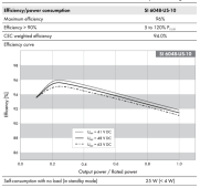
For those with curves published, peak efficiency is often around 25% load. 95% to 96% efficient in example below, depending on battery voltage. Some brands will only quote peak efficiency, so this behavior isn't clear.
There is a no-load power consumption, and then losses putting current through transistors and inductors which is proportional to square of current (W = I^2 x R)

The efficiency vs. watts curve is only valid for an ideal or "real" resistive load, like a heater or incandescent bulb. In that case W = VA. For inductive or capacitive loads like motors, current is out of phase with voltage, and there is more current than the wattage indicates, which causes higher loss. Also for loads which draw non-sinusoidal current, like switch-mode supplies for PCs or LED lamps. Losses can easily be double what was expected.

Often, it is the no-load loss that dominates. Some inverters that can be over 100W.
In the example below it is 25W (per inverter, system could have 1 to 4 inverters.)

There is also an idle mode where it consumes 4W. For this inverter, that is used if batteries are drained at night, then during daytime it wakes up every two hours to see if charging occurs. Some brands use an idle state and wake up to check or loads.

Page 231


1684416399895.png
 
Well, I have data. I just never set it up to look at efficiency.

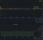
For example, here is the last 24 hours "Power factor for the inverted circuit" and the same graph with the rest of the grid mains outlets for comparison.

1684578034802.png
1684578068706.png
The "red" is the overall "main tails" for the house consumer unit. I believe that is a fridge or freezer bouncing the power factor down every hour or so. It seems to run for longer during the day and less at night. There is also something running through the night with a higher frequency, I might expect the fish tank heater, but it's resistive and runs during the day also! So I don't know what it is.

The really low power factor overnight is because I left a single string of 1W LEDs running as a night light in the room just to see. Well, no surprises on efficiency of that load, 50% and most of that was power factor losses.

On inverter DC to AC efficiencies, I can only really take two sections of graphs to compare. I haven't made a direct DC Out for AC Out graph, though I probably should.

The period with the highest load yesterday was just after it switched back to inverter after a spell of high load which is "Noped" out of by configuration.

It's basically 300W ACOut with a 330W Rating and 335W of DC battery power. There may have been half a dozen watts of solar helping too. Note this period corresponds to a power factor of about 85%. On that, it would seem that the switch mode power supply efficiency curves might have an impact on it's power factor, as when the gaming PC goes up to 300-400W the power factor comes UP with it.

1684578421659.png
 

diy solar

diy solar
Back
Top