diy solar

diy solar

Using Batteries on a circuit (dedicated, disconnected) during outage?

norwich2

New Member
Joined
Dec 5, 2019
Messages
3
SO I'm nearly finished with my PV system. I'll have charged batteries tied to an OFFGrid Inverter. Here is my question: I have 1 circuit that I want to power when the grid goes down. Can I jsut trip that circuit once the power is off, and plug the out jack of the inverter to an open wall socket of that circuit? Then, when power is restored, I disconnect the inverter and turn the circuit back on? Any issues with this? I'm trying to figure out how to connect the two female outlets in this scenario.

It shouldn't matter for this question, but I have a 5400kW Legion3 Solar system with 36 12V (paired into 18 24V) batteries. Each set of 8 12v batteries aggregates through a Legion3 Off Grid Commander and is able to connect to a single OffGrid Inverter.

Thanks!
 
Last edited:
It's not fail safe. This sort of stuff needs to be done properly. Back feeding via an outlet has so many issues that I could take up a whole page writing about it.

Get a proper change over switch fitted at your fuse box / meter box / what ever you call it in your location and a proper disconnect / socket where you can safely plug the inverter in with a proper cord. Think of the inverter as being a petrol / diesel generator and how it would be hooked in.
 
Hi - can you not use an inverter to power this circuit full time and use the grid for the rest. This way you can leave it alone and not have to worry about having to be there when the power trips. Use something like the MPPSolar and you can set it up so that it always uses the utility while the utility is connected but when the utility fails then it switches over to battery. There are 1kva 12v available to do this but you will need to know what power you require.
 
As @thedodgersonline said, your better off with an inverter that has a built in ATS (Auto-Transfer Switch) on the Grid Input AC Line. One which is programmable, programmed to the following:
A) use battery from solar to run an AC Sub-Panel, which is attached to the "Critical circuits".
B) use Grid Power IF batteries reach a pre-programmed discharge threshold.
C) If Grid power fails, use Battery Power.

I looked at the Legion Solar website, limited info on their components and capabilities. It appears their "Off Grid Controller" is the ticket as an ATS function but has limits. https://www.plxdevices.com/product-p/897346002580.htm
(Their Docs PDF)
The "Off Grid" controller is a spiffy ATS idea but limited info: https://drive.google.com/file/d/17ZVkBlTTNF6TaoBUUeRw5iSoC9q4YM-K/view
The Inverter is a 24V/3KW High Frequency unit ? https://drive.google.com/file/d/1yaWklLInrxBUnAbo-_9A5HTGJCRqpCVH/view
The Battery Commander is quite interesting but quite limited so you need many pieces. Limited to 12V Batteries ?https://drive.google.com/file/d/1VULWuTgYJcWe0kjq_etSMN1JRPeH_1zd/view
The docs SUCK ! No Technical or detailed info unless you get into the User Manual and even that is somewhat limited.
The User Manual ; https://drive.google.com/file/d/1bZikGe9UuN2qNRU8hOeqk1wbscYA1997/view

Given this setup with the off-grid controller etc, (which the docs do not mention programmability or anything like that) it's difficult to answer some questions. While there is simplicity in this product line, that also makes it more complicated as well and seems to be a limitation as well... Tied to certain batteries, their Inverter (no charger capability).
 
Last edited:
I just bought one of these switch subpanels and plan to do a little re-wiring, to bring critical circuits to this box.
 
Believe you are talking about a suicide cord.
I made one just for emergency preparedness.
Also wrote up a very simple check list that is stored with the suicide cord.

I've considered that I may be cold, sleepy, in the dark and without my glasses when I have to set this up.
 
So the Legion3 system does have some interesting features, some noted above. Thorough documentation is not their strong suit, however.

Features:
1. Their regulator monitors the lines into the house (direction of flow) and gives the option of not allowing any solar electricity to flow out. This is so you can set up the system and figure out how well it works for you before making that decision. Essentially you have a way of deferring getting the permits and net metering agreement set up until later. At any point later that decision can be made still, those actions taken, and disabling that aspect of the regulator done. BTW- The regulator stays on an UPS and draws little power, which is how it operates as an orchestrator when power goes out.
2. Battery commanders (BCs): These boxes connect with each panel pairs' microinverters and a 24V (2x12V) battery. They have wireless connections (as do teh microinverters and regulator) and there is a software app that lets you set how far you let each battery discharge and how much solar power to provide to batteries vs house while sun is shining. You can, for example, have the batteries feed back out power overnight until they drop to 60% capacity, then let the grid do the rest. Note: the regulator in #1 will detect when the grid goes down and will stop PV power production since that is fed directly into dedicated circuit (s).
3. The OffGrid Controller (OGC) also connects to batteries that the BCs connect to. These devices stay dormant until the regulator detects the grid is down, then they wake up and power the attached Off Grid Inverter (doesn't have to be the one Legions sells directly).

My question was about, in the rare event that the grid goes down, how can I quickly leverage my stored battery power through the OGC and Inverter that are sitting there for no other purpose, and which only activate when the grid goes down? (I figure I can either a) run an extension cord from the invert through my house to certain appliances (except the gas furnace/fan which is hard wired) -or- b) I find a way to connect the Inverter output to the circuit that feeds these specific appliances. I have a single outlet on this 'critical' circuit that is on the wall near the inverter, and I know which breaker it works with in the breaker panel box. Perhaps the "suicide cord" and instruction SmoothJoey notes is exactly what I'm describing, but think I should be able to flip that circuit breaker (isolating the circuit) and plug in that inverter to that one outlet in an outage. This is especially important for the furnace (gas furnace...so little electricity) in winter. That one can't work by extension cord. I don't mine this being a manual process since a few minutes of power loss is not an issue, but a furnace in winter or a refrigerator in summer shouldn't go hours without power.
 
Personally, I would install a small sub-panel which can be powered from the Offgrid controller. Then run whatever circuits you need (never exceeding the amount of wattage / amps you can put out).

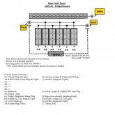
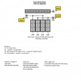
I have a sub-panel that runs my entire cabin (only 120VAC @ 60Hz here) and I used a simple Square-D box and bridge wire to make both legs 120V. It is fed through a 30A (3600w) breaker in the powerhouse. While I am over wired as such, the whole cannot exceed the 3600W / 30A. I have another 120V/15A circuit in the powerhouse to run 1 plug, 2 LED lights and the softstart Grundfos SQ5 deep well pump. See images below.

You could also put a Heavy Duty timer on the AC Line-In which shuts off the AC Inbound during the day (most expensive & highest load time) and on at night so it can top up the batteries. That timer would have to handle the maximum amperage demanded by the charging system from the input AC source !,


Main-Cabin-Panel - LOGICAL.jpg
----
PowerHouse-Panel - LOGICAL.jpg
---

Hope that helps somewhat.
NB: These were drawn up when I put in the first 3KW Inverter, that's changed now...
 
Last edited:
Perhaps the "suicide cord" and instruction SmoothJoey notes is exactly what I'm describing, but think I should be able to flip that circuit breaker (isolating the circuit) and plug in that inverter to that one outlet in an outage.

Its called a suicide cord because there are exposed pins at both ends.
Those exposed pins are energized and that is dangerous.
A better solution is an interlock switch and an inlet(as opposed to outlet).
link to interlock switch
 
This is excellent feedback (not to be confused with backfeed :)) Even if I use a subpanel and interlock I still need to deal with the male-male connection. So would a covered 20A inlet at the wall like this help?:
www.amazon.com/Marinco-200BBIW-ParkPower-Front-Mount/dp/B003VAYK48

Should allow me to more safely connect the live inverter to the dead wall switch when power goes out, I think. My next two questions are then:
1. Is this inlet connector code for the purpose I intend?
2. Isn't there an issue with the white neutral wires still being connected when the breaker's black/hot wire is disabled? In other words, if gird goes down, I flip off my critical circuit (black interrupted), then plug in my inverter to that circuit...doesn't that new current flow through all the neutral wires in the house? Does a subpanel 'break' or separate both neutral and hot wires?
 
Get an electrician to install and/or sign off on your work.

Neutral and ground should be bonded at, and only at the service entrance.
I say that because I don't know if/how your pv system is already integrated.
I am not an electrician and I'm starting to feel like I have said more than I should have.
 
Home Depot has stuff for this on the shelf.

You want a connection that isolates the grid, and has a male socket on it, so A STANDARD EXTENSION CORD connects to it, and it requires a disconnect to connect the plug to a circuit.

You want to be ABSOLUTELY CERTAIN there is no live hot exposed blades... a male male cord will be connected to hot on either end... that is bad.
 
This is excellent feedback (not to be confused with backfeed :)) Even if I use a subpanel and interlock I still need to deal with the male-male connection. So would a covered 20A inlet at the wall like this help?:
www.amazon.com/Marinco-200BBIW-ParkPower-Front-Mount/dp/B003VAYK48

Should allow me to more safely connect the live inverter to the dead wall switch when power goes out, I think. My next two questions are then:
1. Is this inlet connector code for the purpose I intend?
2. Isn't there an issue with the white neutral wires still being connected when the breaker's black/hot wire is disabled? In other words, if gird goes down, I flip off my critical circuit (black interrupted), then plug in my inverter to that circuit...doesn't that new current flow through all the neutral wires in the house? Does a subpanel 'break' or separate both neutral and hot wires?
As long as a PHYSICAL interlock breaks the hot connection from the grid, and only connects your circuit to household wiring when switched to generator position, this will work.

Neutral isn’t required to open in a circuit, because neutral completes a circuit, and isn’t energized above ground potential.
 
One type of Interlock common for vertical main breakers.

s-l1600.jpg


One type common for horizontal main breakers.

s-l400.jpg
 
Last edited:
I have seen furnaces wired with a standard nema 5-15P that goes into a dedicated nema 5-15R.
To power the furnace just unplug from the P and plug it into a extension cord that leads to your generator.
plug to receptacle
 
I have seen furnaces wired with a standard nema 5-15P that goes into a dedicated nema 5-15R.
To power the furnace just unplug from the P and plug it into a extension cord that leads to your generator.
plug to receptacle
I do not know ANY circumstance where this is legal. Appliance cords are not legal to install on fixed in appliances...

This would safely power a furnace in a blackout situation, but it doesn’t help to power a set of circuits in a panel...
 
Back
Top