diy solar

diy solar

Victron Orion Voltage Drop

consolelog

New Member
Joined
Jun 8, 2020
Messages
10
Hey all, I'm finally getting around to diving into this issue.

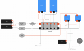
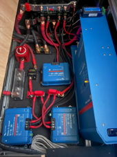
I have a 180amp alternator, connected to 2 Orion 12/12-30 non-isolated chargers to charge my 2x 270AH Lithium house batteries. Whenever the chargers kick in, I can see on the app the voltage input of the Orions drop from ~14V down to 11V, cutting the charging off. The truck's starter battery voltage does not drop when this happens. I've also tried to connect just one Orion, but it still occurs.

The positive from the starter battery to the Orions is ~10ft at 1/0 (I have them branched+fused to 6AWG so they can fit into the Orion ports). The ground is connected to a distributor, which is grounded with a 4/0 wire directly to the truck's frame (not cab chassis).

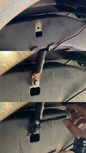
I'm thinking this could be an issue with the ground? This is on a truck camper, where the starter battery + alternator are grounded to the truck's cab chassis. On my house batteries, I've grounded it by tapping directly to the truck's frame. Are these grounds actually different, and the truck's body mounts don't provide enough connections between the frame and chassis?

If so, is it safe to run an additional ground from the starter battery, to a junction that connects the Orions + house distributor? (Green dashed line in my diagram). This would essentially connect the frame ground to the chassis ground

TIA
 

Attachments

  • Screenshot 2024-03-23 at 10.33.05 PM.png
    Screenshot 2024-03-23 at 10.33.05 PM.png
    223.6 KB · Views: 10
It would be better to use the 4/0 ground from the distributor to the starter battery ground and not frame ground. Having multiple ground spots is safe but it causes ground loops which can mess with rf communications. Your battery should be frame grounded and alt should be frame grounded as well.

As it is now you're pulling 60a through the frame and even when trying 30a it's not working. Are you certain you have it properly grounded to the frame? When frame grounding you should be connected to steel and should use a wire brush or something to remove any paint or debris then attach. Typically I've drilled through the frame and wire brushed both sides then used used a bolt and nut with the lug torqued down. This gives the bolt, the nut and the lug a lot of contact room on both sides.

I would do it as you propose with just 1 Orion turned on and see if it doesn't drop, then both and see.

I have 6 orions running through frame ground 40ft over 180a at 24v.
 
Hi @consolelog

Sure, your ground or any other connection could be “an” issue.

The alternator & vehicle control “regulator” / computer can be an issue. You did not note your truck type or if it is a smart alternator etc.

I have build out 2 Ram Promasters; 180amp & 220amp alternators ( not smart systems ). I use chassis return negative grounds on both of them with zero issues. IMO and tested thru voltage drop, the large mass chassis provides a pretty good negative connection back to the alternator ( which also is negative chassis ground BTW ). I believe if the chassis is good enough for the vehicle alternator & starter battery to use as a singular path of completing that charge circuit, then why is adding a house battery by chassis negative return a bad idea ? 🤷‍♂️

You could add a negative cable to Orions & house to the starter battery negative & if that fixes your problem then the issue is with your chassis & grounding system.

Sometimes posting photos can help. The Distributor is what ? I am wondering depending upon your setup if the positive red wire going to the distributor can make it to your shutoff battery switch to bypass the distributor for “testing” reasons?

The other thing that I’m not sure about is your BMV ? What is that & what is the red wire going to the Distributor? If that is a Victron 712 then when you shut off the house battery you are not also turning off the BM ?
 
Last edited:
Hi @consolelog

Sure, your ground or any other connection could be “an” issue.

The alternator & vehicle control “regulator” / computer can be an issue. You did not note your truck type or if it is a smart alternator etc.

I have build out 2 Ram Promasters; 180amp & 220amp alternators ( not smart systems ). I use chassis return negative grounds on both of them with zero issues. IMO and tested thru voltage drop, the large mass chassis provides a pretty good negative connection back to the alternator ( which also is negative chassis ground BTW ). I believe if the chassis is good enough for the vehicle alternator & starter battery to use as a singular path of completing that charge circuit, then why is adding a house battery by chassis negative return a bad idea ? 🤷‍♂️

You could add a negative cable to Orions & house to the starter battery negative & if that fixes your problem then the issue is with your chassis & grounding system.
I don't see how a smart alternator would cause any affect if connected directly to the starter battery. That battery would need to be drained if 11v. Although I don't understand smart alternators
 
I don't see how a smart alternator would cause any affect if connected directly to the starter battery. That battery would need to be drained if 11v. Although I don't understand smart alternators

Well ya know @justinm001 when attempting to help others from afar & over the internet & without all the information ,,, we are kinda shooting in the dark.

Before setting up my 1st Promaster, I researched the alternator & Ram’s computer control of it as much as I could (without Ram’s Engineering being disclosed - corporate secret squirrel stuff). I also do not see how ,,, as you say ,,, but trying to provide the OP some issues that could be.

I tend to build as simple of systems as possible. If an issue arises, I can usually pinpoint the problem with a multimeter very quickly.
 
Last edited:
It would be better to use the 4/0 ground from the distributor to the starter battery ground and not frame ground. Having multiple ground spots is safe but it causes ground loops which can mess with rf communications. Your battery should be frame grounded and alt should be frame grounded as well.

As it is now you're pulling 60a through the frame and even when trying 30a it's not working. Are you certain you have it properly grounded to the frame? When frame grounding you should be connected to steel and should use a wire brush or something to remove any paint or debris then attach. Typically I've drilled through the frame and wire brushed both sides then used used a bolt and nut with the lug torqued down. This gives the bolt, the nut and the lug a lot of contact room on both sides.

I would do it as you propose with just 1 Orion turned on and see if it doesn't drop, then both and see.

I have 6 orions running through frame ground 40ft over 180a at 24v.

I was hoping to not have to run a long 4/0 back to the chassis. The camper is sitting on the frame, and the only safe point without a ton of work, is to the designated ground on the firewall. The current ground is 2ft, vs 10ft needed to make that route. (blue line in the pic is my current ground, vs green)

I've attached how i've grounded to the frame - sanded well before applying a rubber coating to prevent rust.

I'll try hooking up a test ground today, from the firewall to the Orion to see if I really need to do that.

I do have the isolated version of the orion ordered as well, and might just run a smaller dedicated ground to that (hoping i don't have to and can return it)

Edit: The area between the rear of the cab chassis and the camper has 2 walls between them. In order to properly asses and have enough room for a ground back there... would mean I'd have to remove the camper (which would be a nightmare). Hence, the green path to a factory ground.
 

Attachments

  • FFA17A8B-DB9F-4F6D-A089-5DB829B40393.jpeg
    FFA17A8B-DB9F-4F6D-A089-5DB829B40393.jpeg
    111.5 KB · Views: 7
  • IMG_4348.jpeg
    IMG_4348.jpeg
    291.2 KB · Views: 7
Last edited:
Hi @consolelog

Sure, your ground or any other connection could be “an” issue.

The alternator & vehicle control “regulator” / computer can be an issue. You did not note your truck type or if it is a smart alternator etc.

I have build out 2 Ram Promasters; 180amp & 220amp alternators ( not smart systems ). I use chassis return negative grounds on both of them with zero issues. IMO and tested thru voltage drop, the large mass chassis provides a pretty good negative connection back to the alternator ( which also is negative chassis ground BTW ). I believe if the chassis is good enough for the vehicle alternator & starter battery to use as a singular path of completing that charge circuit, then why is adding a house battery by chassis negative return a bad idea ? 🤷‍♂️

You could add a negative cable to Orions & house to the starter battery negative & if that fixes your problem then the issue is with your chassis & grounding system.

Sometimes posting photos can help. The Distributor is what ? I am wondering depending upon your setup if the positive red wire going to the distributor can make it to your shutoff battery switch to bypass the distributor for “testing” reasons?

The other thing that I’m not sure about is your BMV ? What is that & what is the red wire going to the Distributor? If that is a Victron 712 then when you shut off the house battery you are not also turning off the BM ?

It's a 99' Tacoma. No smart alternator here. I haven't completely ruled out the alternator being the issue, but it should have 130amps at idle: https://www.dcpowerinc.com/products...a-3-4-l-5vz-fe-v6?_pos=4&_sid=dc9e06d86&_ss=r

Distributor is the Victron Lynx Distributor.
Yes the BMV is the Victron 712. But it does turn off when the batteries are shut off.

The wires leading out to the left of the picture are to the battery bank. Ignore the extra large black wire going left, that's for the shore power to the multiplus
 

Attachments

  • IMG_1289-Edit.png
    IMG_1289-Edit.png
    1.4 MB · Views: 8
I was hoping to not have to run a long 4/0 back to the chassis. The camper is sitting on the frame, and the only safe point without a ton of work, is to the designated ground on the firewall. The current ground is 2ft, vs 10ft needed to make that route. (blue line in the pic is my current ground, vs green)

I've attached how i've grounded to the frame - sanded well before applying a rubber coating to prevent rust.

I'll try hooking up a test ground today, from the firewall to the Orion to see if I really need to do that.

I do have the isolated version of the orion ordered as well, and might just run a smaller dedicated ground to that (hoping i don't have to and can return it)

Edit: The area between the rear of the cab chassis and the camper has 2 walls between them. In order to properly asses and have enough room for a ground back there... would mean I'd have to remove the camper (which would be a nightmare). Hence, the green path to a factory ground.

Isolated and non-isolated doesn't matter if you have both systems frame grounded. Its only helpful in specific applications where you wouldn't want to share ground.

Since it's a 99 you might want to dig into your chassis ground from the alternator and the battery. It's entirely possible they aren't grounded well or are corroded.

Ah forgot to mention, I've replaced all the critical engine wires to 1/0 (alternator, starter, fuse box, grounds, etc).

There's no dedicated copper cable running from the truck cab's chassis to the frame.
It's connections are mainly from the body mounts, engine mounts, (and i'm sure some other small contacts here and there. - I haven't checked those, but I'm guessing they look pretty worn / rusted.
There should be a ground cable from the engine to the chassis. Body and engine mounts typically are rubber or other non conductive material designed to absorb vibrations. They purposely use rubber everywhere possible. Is the starter battery frame grounded?

Id dig through all this and find your weak point in the grounding, fix this then use the orions to know it's resolved.

The starter battery is not frame grounded, just chassis grounded. I looked at the FSM electrical schematic for the Tacoma and there are no factory grounding points to the frame. Just 2 wires: from the starter + chassis, and engine block to the chassis (all of these chassis points are under the hood). The Tacoma isn't a unibody - its body on frame.

But good news...I had a 1/0 laying around, ran it through my driver's window into the camper and that worked. Starter battery/chassis stud <-> Orion/Lynx Distributor stud. So the frame really wasn't sending it all back to the starter battery - I should note, I did see the charge working sometimes. Like 10% of the time when I was trying to diagnose.

Follow up question - I'm going to keep that 4/0 frame ground since it's already there, but will add that additional one to the chassis/starter battery to the Lynx Distributor.

Does that wire size need to match the potential of my entire house system? Or just the expected return of the amps I'm pulling from the Orions? It's been a while since I calculated (and I believe I oversized) but all the large components are using 4/0.
  • 2 x 270AH
  • Multiplus Compact 2000
  • 2 x Orion 30, max 60amps. This is connected by a 10-13ft 1/0 positive to the starter.
Hoping I can just use the 1/0 I have on hand and not shell out for a longer 4/0.

Thanks for the help so far!

EDIT: Did some searching and it looks like some people add an additional ground from the chassis to their frame on these old trucks... I guess I could go that route as well.
 
Last edited:
Looks like you already found problem. I disagree with using the chassis or frame for "ground"... what it sounds like you mean is "NEGATIVE/NEUTRAL RETURN", and not actually the electrical concept of ground. Incorrectly using these terms, as if they are all the same in an electrical circuit, leads to incorrect thinking. They are not the same in a mobile system.

Here is the "approved" summary for Grounding Basics for a Mobile System, posted on this very website under basic reference info. Your mobile system should be using a negative cable from the orion chargers to house battery, and then back from charger to start battery. The non isolated aspect of that charger means it does have negative pass thru from house to starter. There should only be one single "bond" between your negative system and your ground, the chassis, and that should be at the start battery. (Yes I know engine and alternator are both tapped to chassis for their negative path). The non isolated charger means that the house system bond should actually be the single connection to chassis at the start battery.

As justin said above, multiple connections to chassis results in ground loops. Assuming good solid electrical connections between engina area chassis and rear frame is a poor assumption, things are mounted with rubber vibration isolators and bolts, the sides of bolts going thru frame are NOT a good electrical connection. And also, 60A is a lot to expect to balance through a chassis.
From all the posts Ive ever read, the #1 biggest cause of mobile system electrical issues is people using multiple chassis connections to act as their neutral/negative. Connections are poor, connections corrode, connections move around and loosen, circuit paths don't flow the current expected, multiple ground loops are created, shorts are hard to trace, current flows through all possible paths causing electrical voltage potential issues for delicate things. It's a bad way to do it.

Just run both cables, positive and negative, everywhere, stop trying to scrimp on your negative. Calculate your circuit amp flows, and run actual known good copper cable to carry the entire circuit, instead of assuming a chassis connection will somehow all be good.

Read this file on the actual best mobile setup. Link is in Befinners Forum, Resources.
Thanks for the detailed response! Will put that 4/0 negative in.
 
Looks like you already found problem. I disagree with using the chassis or frame for "ground"... what it sounds like you mean is "NEGATIVE/NEUTRAL RETURN", and not actually the electrical concept of ground. Incorrectly using these terms, as if they are all the same in an electrical circuit, leads to incorrect thinking. They are not the same in a mobile system.

Here is the "approved" summary for Grounding Basics for a Mobile System, posted on this very website under basic reference info. Your mobile system should be using a negative cable from the orion chargers to house battery, and then back from charger to start battery. The non isolated aspect of that charger means it does have negative pass thru from house to starter. There should only be one single "bond" between your negative system and your ground, the chassis, and that should be at the start battery. (Yes I know engine and alternator are both tapped to chassis for their negative path). The non isolated charger means that the house system bond should actually be the single connection to chassis at the start battery.

As justin said above, multiple connections to chassis results in ground loops. Assuming good solid electrical connections between engina area chassis and rear frame is a poor assumption, things are mounted with rubber vibration isolators and bolts, the sides of bolts going thru frame are NOT a good electrical connection. And also, 60A is a lot to expect to balance through a chassis.
From all the posts Ive ever read, the #1 biggest cause of mobile system electrical issues is people using multiple chassis connections to act as their neutral/negative. Connections are poor, connections corrode, connections move around and loosen, circuit paths don't flow the current expected, multiple ground loops are created, shorts are hard to trace, current flows through all possible paths causing electrical voltage potential issues for delicate things. It's a bad way to do it.

Just run both cables, positive and negative, everywhere, stop trying to scrimp on your negative. Calculate your circuit amp flows, and run actual known good copper cable to carry the entire circuit, instead of assuming a chassis connection will somehow all be good.

Read this file on the actual best mobile setup. Link is in Befinners Forum, Resources.

I agree but it's important to mention that many oem systems are not home run neutral and utilize the frame as a negative return. Alternator is a great example. Many internal components are like stereos and such. It solves the ground loop issue as everything is connected to the frame only.

But this is the cheap and easy way, not the best or most stable. My Orions are the only things frame grounded as the coach was built this way with 2/0 direct from alt 40ft to front. Also on a HD 40,000 lb bus all made stainless steel frame there's a ton of metal to spread the power.

Yup;

When the “Alternator” used the frame to close the negative side of the circuit & so does the starter battery, it is hard to understand why utilizing the frame is not sanctioned.

Of course if bad connections are made along that path or corroded it isn’t going to be good.

The final work on such an installation would be the “gismo’s” manufacturer ,,, in this case Victron. If they sanction “Negative Path Return” via chassis I suppose it is ok ,,, If they don’t allow it then a black negative cable of the right size should be installed.

I have a Kisae 1250 & obtained in writing from Kisae that I could utilize the chassis as the “Negative Path Return”. In addition “for safety” Kisae wants the “gismo’s” box “grounded” to the chassis.

Chassis negative return path instead of a big black cable 🤷‍♂️ ,,, Ya better have solid frame connections & a great chassis path back to the starter battery negative terminal ,,, or there will be issues.

On the distribution side of things ,,, best to run red & black “home run” to the dc fuse block. I never chassis return anything but the DC2DC charger
 
BM712 Smart;

IMG_1245.jpeg


As the Victron supplied positive has an inline fuse & the install diagram details a direct connection to the positive battery terminal ,,, YMMV if you install it in the maner you have.

The main reason why I install it per Victron’s diagram is I have my Van House Batteries shut of with the master switch when the van is not being used “storage mode”. I can walk by the outside of the van & check the battery status on my phone even with the master battery switch off.

2nd reason is I have AGMs & the temperature sensor is actually the red positive battery terminal temp probe, from Victron.
 
Ah forgot to mention, I've replaced all the critical engine wires to 1/0 (alternator, starter, fuse box, grounds, etc).

There's no dedicated copper cable running from the truck cab's chassis to the frame.
It's connections are mainly from the body mounts, engine mounts, (and i'm sure some other small contacts here and there. - I haven't checked those, but I'm guessing they look pretty worn / rusted.

Ya, I’m guessing you are already “on the path” to discovering your issue.

As @Dave in AZ posted above ,,, there is a lot of issues you can have if the path is not 100%.
 
BM712 Smart;

View attachment 204449


As the Victron supplied positive has an inline fuse & the install diagram details a direct connection to the positive battery terminal ,,, YMMV if you install it in the maner you have.

The main reason why I install it per Victron’s diagram is I have my Van House Batteries shut of with the master switch when the van is not being used “storage mode”. I can walk by the outside of the van & check the battery status on my phone even with the master battery switch off.

2nd reason is I have AGMs & the temperature sensor is actually the red positive battery terminal temp probe, from Victron.
The smartshunt uses like 1mA so wired your way would be like 1ah every month max. Not sure if same for the Bmv since it has a screen. . At some point I plan on measuring my parasitic draw for all these small things and planning on calculating what needs to be shut down when. Idk why Victron stuff is all in ah when their stuff has such a huge voltage range (6.5-70v). Does the Victron equipment really use 4x as much power when running on 48v versus 12v?
 
Back
Top