Taking into consideration the accurate responses above let me share with you that I have a Magnum 4024 inverter/charger in my RV that can handle both a fridge and AC at the same time. The wiring suggested by Magnum is 2/0. In your position, you may have to replace three things, the inverter, BMS and wiring. I would start with the wring and switch to 2/0 with your inverter and battery as close together as possible. If that doesn't work, or even if it does work, your next weak link is going to be the BMS. I bypass the BMS problem by connecting my BMS to a contactor/relay but there are also large BMS units available. If these two steps, (which you should take regardless) do not work then you know you have a problem with the inverter or possibly the freezerWe have one string of 3 of 280w panels, they reach around 25 volts, showing 100% on the charge controller soon after the sun is up. No issues running things as long as there is sun. But the startup in the morning of the freezer on the timer is when we have the issue.


You are using an out of date browser. It may not display this or other websites correctly.
You should upgrade or use an alternative browser.
You should upgrade or use an alternative browser.
What’s the best inverter?
- Thread starter ShaneT
- Start date
sunshine_eggo
Happy Breffast!
How do I know the correct torque?
Possibly listed on the inverter or battery spec. If not, look up torque for the thread sizes (diameter of threads, NOT hex head) used and select something from the low end.
We have one string of 3 of 280w panels, they reach around 25 volts, showing 100% on the charge controller soon after the sun is up. No issues running things as long as there is sun. But the startup in the morning of the freezer on the timer is when we have the issue.
"100% on the charge controller" is meaningless. It's purely based on voltage, and it could read 100% even when your batteries are dramatically lower.
Voltage based SoC is WORTHLESS UNLESS the batteries have sat without any load or charge on them for 2+ hours.
I suspect that you have the following in play:
- poor connections
- 2awg wire
- low battery
Or your 3000W inverter is a turd.
")
I just double checked, the right light and audible alarm signify that there is low voltage protection on the inverter.What does the red light signify?
It could be low voltage disconnect or it could be overload or it could be something else.
John Frum
Tell me your problems
- Joined
- Nov 30, 2019
- Messages
- 15,233
Confirms my hypothesis.I just double checked, the right light and audible alarm signify that there is low voltage protection on the inverter.
Now lets see about a remedy.
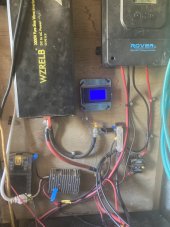
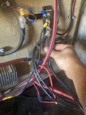
Please post a picture of the entire wire path between the inverter and the battery.
Okay, I think I’ll try with the connections first….I don’t understand how to set the torque though…what kind of wrench do you use for that?? All I have are socket and end wrenches….Possibly listed on the inverter or battery spec. If not, look up torque for the thread sizes (diameter of threads, NOT hex head) used and select something from the low end.
"100% on the charge controller" is meaningless. It's purely based on voltage, and it could read 100% even when your batteries are dramatically lower.
Voltage based SoC is WORTHLESS UNLESS the batteries have sat without any load or charge on them for 2+ hours.
I suspect that you have the following in play:
One or more of those is causing the voltage the inverter sees to drop below the disconnect voltage.
- poor connections
- 2awg wire
- low battery
Or your 3000W inverter is a turd.
As far as the batteries are concerned, do I need to read the levels on the BMS when the error occurs to find out if it’s a low battery issue? All of my cells are at a healthy level right now and I have a balancer to manage them that I monitor through the app.
Confirms my hypothesis.
Now lets see about a remedy.
Please post a picture of the entire wire path between the inverter and the battery.
Attachments
You can also feel for heat at the connections and/or check voltage at each connection to look for problems. I wouldn't worry about torque right now, I would just make sure everything is snug.Okay, I think I’ll try with the connections first….I don’t understand how to set the torque though…what kind of wrench do you use for that?? All I have are socket and end wrenches….
As far as the batteries are concerned, do I need to read the levels on the BMS when the error occurs to find out if it’s a low battery issue? All of my cells are at a healthy level right now and I have a balancer to manage them that I monitor through the app.
I can't see the battery or its connections which could be an issue.
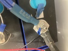
The shunt(which in the wrong place) has a ring terminal underneath the inverter lug.
Switch those so that the inverter lug is on the bottom and test again.
Attachments
Is this the shunt? If I’m understanding correctly, it looks like the inverter lug is on the bottom. Or am I mistaken? Also, where does the shunt need to go to be in a better place?I can't see the battery or its connections which could be an issue.
The shunt(which in the wrong place) has a ring terminal underneath the inverter lug.
Switch those so that the inverter lug is on the bottom and test again.
Attachments
John Frum
Tell me your problems
- Joined
- Nov 30, 2019
- Messages
- 15,233
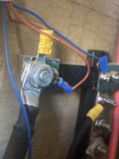
Yes that is the shunt.Is this the shunt? If I’m understanding correctly, it looks like the inverter lug is on the bottom. Or am I mistaken? Also, where does the shunt need to go to be in a better place?
The shunt should be between the battery and everything else.
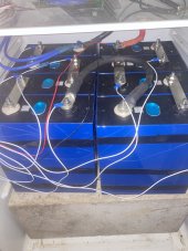
Before we change that we need to understand where that big black wire off the battery negative is going.
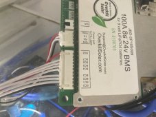
The in the picture I am holding the black wire that goes to the negative terminal on the battery where the BMS is connected.You have a double blue wire going to the negative terminal and a black wire.
Where does the black wire go?
I see the double blue wire goes to your bms.
Attachments
John Frum
Tell me your problems
- Joined
- Nov 30, 2019
- Messages
- 15,233
I think that wire is in parralel with our BMS effectively bypassing the protection your bms offers.The in the picture I am holding the black wire that goes to the negative terminal on the battery where the BMS is connected.
I wonder if someone put that in as hack to fix the inverter low voltage trip problem.
You system needs to be fixed.
I am new at this stuff…..and did the install myself. The ways it’s connected isn’t a hack, it’s just the way I connected it….Is there any way you would be willing to help guide me to fix it?I think that wire is in parralel with our BMS effectively bypassing the protection your bms offers.
I wonder if someone put that in as hack to fix the inverter low voltage trip problem.
You system needs to be fixed.
curiouscarbon
Science Penguin
- Joined
- Jun 29, 2020
- Messages
- 3,027
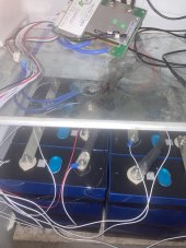
is BMS C- connected to busbar negative?
is BMS B- connected to pack negative?
is mystery black cable connected to busbar negative?
is mystery black cable connected to pack negative?
it is hard to tell for me
ideally the BMS would be the only thing between Pack Negative (lowest voltage cell post) and Busbar Negative so it can fully disconnect power
the shunt will only monitor the inverter power use, sorry if this is inane to mention
John Frum
Tell me your problems
- Joined
- Nov 30, 2019
- Messages
- 15,233
The problem is that fixing that will make your system less able to cope with the inverter draw.I am new at this stuff…..and did the install myself. The ways it’s connected isn’t a hack, it’s just the way I connected it….Is there any way you would be willing to help guide me to fix it?
But yes I will help.
How about tomorrow?
I've got a busy afternoon.
sunshine_eggo
Happy Breffast!
I am new at this stuff…..and did the install myself. The ways it’s connected isn’t a hack, it’s just the way I connected it….Is there any way you would be willing to help guide me to fix it?
The torque on all those 10mm nuts should be 6-7 Nm. If any of those are loose, problem. For the love of all that is holy, do NOT over-tighten them and destroy a terminal.
Harbor freight sells a workable 1/4" torque wrench that works in this range.
Okay, yes, tomorrow would be great if you have time.The problem is that fixing that will make your system less able to cope with the inverter draw.
But yes I will help.
How about tomorrow?
I've got a busy afternoon.
So this wiring issue is not my only issue? You think I need a better inverter also? Something with more surge power? Possibly more volts?
is BMS C- connected to busbar negative?
is BMS B- connected to pack negative?
is mystery black cable connected to busbar negative?
is mystery black cable connected to pack negative?
it is hard to tell for me
ideally the BMS would be the only thing between Pack Negative (lowest voltage cell post) and Busbar Negative so it can fully disconnect power
the shunt will only monitor the inverter power use, sorry if this is inane to mention
Attachments
Similar threads
- Replies
- 4
- Views
- 258
- Replies
- 3
- Views
- 155
- Replies
- 2
- Views
- 301