diy solar

diy solar

What is the input source for Batrium's Solid State relays?

hummmingbear

New Member
Joined
Feb 8, 2022
Messages
172
I have been scouring their documentation and google trying to find how their Solid State Relay's are powered. The only details I see is that they have a + and - on the schematic. But it is unclear where the INPUT source is for that. I have tried providing power to the expansion boards two INPUTS and manually enabling the relay, but my multimeter does not show any voltage. I am really annoyed at how poor their products are documented...or maybe I'm just dull.

This is for the Expansion Board 3. Pinout below, any help appreciated.
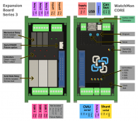
1661738234104.png
 
You are talking about SSR 5-7?
When you say powered, what specifically are you asking? The "control" side is powered by the board and the main Core.

The outputs, you put power in on the "positive" and get switched power out on the "negative"

Edit: yes, 1000 times yes, Batrium needs to work on their documentation.
 
I have been scouring their documentation and google trying to find how their Solid State Relay's are powered.
Based on the diagram provided it seems like the mechanical relays as well as the SSR's are "Dry Contact" type meaning the Batrium set up menu gives the user some options as to what battery conditions will close or open the relay but there is no voltage unless the user connects a source to either the Com or NO terminal block. The Pos Neg labels on the SSR's are only there to indicate the current flow direction since they seem to be DC SSR's. Same scenario, the Batrium board is not providing any power only activating or deactivating the SSR gate.
This is actually a good thing since it gives the user many voltage-current options (up to the limit of the relay or SSR) rather than some arbitrarily chosen voltage value by a Batrium engineer.
 
I use Relay 1 (expansion board) to trigger the shunt-trip on my ABB SACE S3 - as the overall powerwall kill breaker.

Relay 1 is open but will close when the assigned event occurs - in my case I have "Critical Fault" assigned.
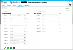
1661740211468.png
I supply my own power from the battery. Batrium itself doesn't provide power to it - just toggles it.

-------------
There may be other operations, and as you say the docs aren't so clear, but I never went further than just using Relay 1.

TMI: The thing that set me back for a while is shunt-trips only needs a "pulse" - confused me as it seemed like a sophisticated bit of circuitry. But it just means that once a shunt-trip is tripped (<sec) it doesn't need power anymore. In the ABB SACE S3 case, the tripping mechanism doesn't use power once it's tripped. So you can directly tap 24v (trip coil voltage on mine) from a 48v powerwall, route it thru the relay - and since it's only 1 sec of load it won't unbalance the battery.
 
Yes, your description is accurate. A relay or SSR is simply a switch that can be remotely controlled, the Batrium just toggles it between states.

Regarding the shunt trip breaker pulse. Some manufacturers have a built in disconnect so when the breaker trips, power is cut off from the RT coil and it will not overheat and burn out. Midnight Solar on the other hand uses Carling Technologies Type F breakers that do not have the internal disconnect feature. I designed a simple PCB control board that would provide the necessary PULSE to trip the breaker then shut off. Of course it would have been easier to select a different brand of breaker but that would not be in the DIY spirit.
Batrium does have integrated functionally to support a single pulse of the relay to trip the breaker. It works well on my Midnight/Carling Tech breaker.
 
Batrium does have integrated functionally to support a single pulse of the relay to trip the breaker. It works well on my Midnight/Carling Tech breaker.
Good to know, thanks for the clarification. I've not read Batrium documentation myself, only know what has been discussed here.
 
You are talking about SSR 5-7?
When you say powered, what specifically are you asking? The "control" side is powered by the board and the main Core.

The outputs, you put power in on the "positive" and get switched power out on the "negative"

Edit: yes, 1000 times yes, Batrium needs to work on their documentation.
Okay, that is very confusing that the positive is the input and the negative is the output, but thank you for that explanation.

What was odd is when I manually switched the SS relay on, my multimeter did not show continuity between positive and the negative, does it need voltage for it to work?
 
Last edited:
My contactor requires ~48 volts, so I can't use the regular relays on the board, I have to use the solid state relays. When the contactor has power provided to it, it will allow power through, but with no power it will immediately disconnect. I want to program the solid state relay to provide either a positive switch or negative switch to the relay. I can hook up the other wire directly to the battery (~48v)
 
Not understanding what you are asking but would like to get your question answered.
Sorry, was replying with my phone and not explaining well. On my laptop now.

First I just want to confirm if I provide a positive from my battery (fused) to the + on the SSR, when the relay is switch (on/closed) it will continue the + connection to the - connection on the SSR? If I'm understanding correctly, then I would have a negative lead from my battery to the contactor, and the positive lead would be coming from the (-) labeled connection on the SSR?

My second question is just making sure I select the correct setting on Batrium for faults, but essentially I would like any fault to disconnect the SSR connection (cutting power to my contactor).
YES, to the first question.

The SSR should open if Cell Voltage, Current or Temp become equal or exceed either the high or low Fault (Trip) value.
 
YES, to the first question.
Thank you...and wow that in a bit confusing. Am I wrong that a better label for the SSR would be Input and Output, or something of the likes? I'm used to COM, NO, NC ports, but understand that this is a bit different. The SSR's I've seen online
The SSR should open if Cell Voltage, Current or Temp become equal or exceed either the high or low Fault (Trip) value.
Do you know what specific Batrium setting that is? They only list so many for the SSR, and they don't specify whether it makes the circuit open or closed
 
If you click on the little face with headset, looks like a guy working tech support to me, it is a link to the related Batrium support page.
Green circle at the top right is a link to: https://wiki.batrium.com/toolkit/hardware/expansion
Scroll down, and they list all the options to drive output.
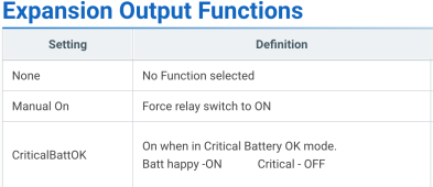
It sounds like you want "CriticalBattOK" the relay is on when the battery is happy, opens when there is an issue.

1661748052840.png

Thank you...and wow that in a bit confusing. Am I wrong that a better label for the SSR would be Input and Output, or something of the likes? I'm used to COM, NO, NC ports, but understand that this is a bit different. The SSR's I've seen online
It is very odd, I believe they were trying to ensure everyone got the polarity correct. A user could connect the COM to ground and my understanding is that would not work with these SSRs.
 
T
If you click on the little face with headset, looks like a guy working tech support to me, it is a link to the related Batrium support page.
Green circle at the top right is a link to: https://wiki.batrium.com/toolkit/hardware/expansion
Scroll down, and they list all the options to drive output.
It sounds like you want "CriticalBattOK" the relay is on when the battery is happy, opens when there is an issue.

Thank you! I'm really grateful to find such good help from a stranger. You saved me a bit of time and headache here. I've tested the SSR and confirmed it's working as you described. Going to setup the relay to work with CriticalBattOK now. Much appreciated!
 
Thank you...and wow that in a bit confusing. Am I wrong that a better label for the SSR would be Input and Output, or something of the likes? I'm used to COM, NO, NC ports, but understand that this is a bit different. The SSR's I've seen online

Do you know what specific Batrium setting that is? They only list so many for the SSR, and they don't specify whether it makes the circuit open or closed

1676734073108.png
 
Back
Top