• Have you tried out dark mode?! Scroll to the bottom of any page to find a sun or moon icon to turn dark mode on or off!

diy solar

diy solar

What REALLY requires a pure sine inverter?

rin67630

Solar Addict
Joined
Apr 29, 2020
Messages
1,117
Location
Nort-Rhine-Westphlia Germany
Pure sine inverters are expensive, but for which usage are they REALLY required?

Some will say: for powering sensitive electronics...
Did you really consider what mainly happens in >95% of today's electronics?
The AC input signal is rectified to DC before going to a DC-DC converter.
So it makes exactly NO difference if they get a pure sine or a modified sine.

Pure sine inverters are not only more expensive, they have a much higher quiescent current (no load loss) and a lower efficiency.

For which usages did you really experience that a pure sine inverter is absolutely required?
 
It really depends on the construction of the power supply. Active PFC power supplies which are becoming common are particularly problematic. If I plug my laptop power supply into a modified sine wave inverter, it works, but makes a loud high pitched noise, and quickly gets very hot. I have not run it except for a minute or two, but I expect it would quickly fail. My old Mac computer did not work at all with modified sine wave.
 
Why bother with anything other than sinewave? If one wants to save money eliminate AC and go with DC. Edison wasn't completly wrong about DC?
 
I dont know a whole lot, but I know somehow my parents have burned out a half-dozen coffee makers using their Magnum Modified Sine inverter in their motorhome.

Now, I can't prove the inverter caused the damage, but if it looks like a duck and quacks like a duck...
 
Some will say: for powering sensitive electronics... YES I 100% SAY THAT
Did you really consider what mainly happens in >95% of today's electronics? YES I'VE SPENT MORE THAN 40 YEARS ON IT
The AC input signal is rectified to DC before going to a DC-DC converter.
So it makes exactly NO difference if they get a pure sine or a modified sine.
Your statement is an over-simplification. When you rectify pure AC you get a DC pulse that is almost contiguous and the use of capacitors help to mitigate the pulsing of the voltage and current at the frequency expected without clipping, jitter, higher total harmonic distortion and blank-outs. (Blanking is a dead time between the rise and fall of two consecutive wave forms where there is no rise, no fall, just nothing. You can still have 60hz with blanking, but you'll still get straight line dead time.)

A modified wave inverter uses less post processing from the digital signal creating the "wave form" and therefore draws less power at idle, and runs cooler, seemingly more efficient. It's cheaper to mass produce. However it most often has the high total harmonic distortion, clipping, jitter and especially blanking between the waves forms.

A pure sine wave inverter uses more power at idle and much more post processing of the digital pulses in order to deliver the smooth and clean AC wave form.

Circuit designers use calculations based off of a pure sine wave in the rectification and filtering in a power supply. Assuming the 120v or 240v line voltages are clean and purely sinusoidal the psu are specked around the minimum parts and space to provide the various voltages required to operate the TV, VCR, DVR, laptop etc. There is no need to employ additional rectification, filtering, ground plane and capacitance etc. Often there is more than one output voltage of the psu in a device, there may be several. A typical PC psu uses 3.3v, 5v with higher current and 12v. Is anyone willing to fry their PC or HAM equipment in order to save money on a chintzy inverter?

Which is better quality - a class D amplifier or a class A amplifier? Class A is less efficient and runs hotter by design in order to produce the cleaner sound with much lower THD.

The effects passed on by modified wave form inverters can cause noise, digital interference and additional heat in electronic devices.

Board design is more complicated than your trip to Radio Shack to buy a simple rectifier in your overly simple statement.
 
It so happens today is my first day running a PSW inverter in my off grid shop and home. I replaced a Krieger 1100w MSW with a Victron 1000w PSW.

First thing we noticed was the dorm fridge was quieter and the back was warm to the touch. When powered. by the MSW the back of the refrigerator was always too hot to touch.

The bench top sander and dremel were snappier and more responsive, my wife noted her drill seemed smoother. All the tools ran MUCH cooler.

The laptop usally hums from the power brick and it becomes quite hot, well, today there was no noise from the power block and it was barely warm.

Just what we noticed after 2 years of the MSW daily use vs today on a PSW.
 
When you rectify pure AC you get a DC pulse that is almost contiguous and the use of capacitors help to mitigate the pulsing of the voltage and current at the frequency expected without clipping, jitter, higher total harmonic distortion and blank-outs...
ROTFL!
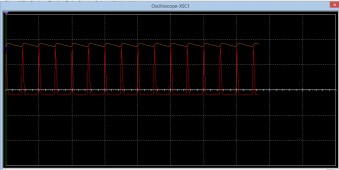
When you rectify a pure sine AC Signal, followed by capacitors, you get tremendous current pulses having nothing common with a sine again. It clips all the time on the peak of the sine waves blanking out in between..
1620793299572.pngThe higher the smoothing capacitors, the bigger and shorter the current pulses.
Tell me about harmonic distortion and jitter...
ROTFL.
Often there is more than one output voltage of the psu in a device, there may be several. A typical PC psu uses 3.3v, 5v with higher current and 12v.
Even more: every current CPU runs on different -variable- voltages ranking from 1.1V to 3.3V and a few outputs are 5V. 12V is a relic of the 80's you won't find it any more.
... and how do you believe these various voltages are realized?
Do you think there is an old transformer with different voltage outputs like at Edisons' time?
?
The computer PSU has a DC rectifier, followed by a main isolated high frequency DC-DC converter, followed by separate buck converters, one for each voltage. The CPU has its own programmable DC-DC converter.
So once the primary input voltage is rectified, everything behind is 100% the same.
 
Last edited:
  • Like
Reactions: Cal
eliminate AC and go with DC.
That's very true.
Most contemporary PSUs will work better if fed with DC, since they will get already rectified current.
There is only one BIG caveat: Switching >100V DC is not trivial, you get tremendous sparks.
AC or modified sine has 0V times in between that erases the spark.
 
I dont know a whole lot, but I know somehow my parents have burned out a half-dozen coffee makers using their Magnum Modified Sine inverter in their motorhome.
That is well possible on coffee makers with electronic timers (fed by a capacitive voltage dropper cf. my post #2).
It really depends on the construction of the power supply. Active PFC power supplies which are becoming common are particularly problematic.
Active power supplies which are now quasi 100 of all PSUs are particularly well suited to be fed with modified sine.
 
Did you test the Power supply with Active PFC fed by modified sine wave to see what the result is? Does it still maintain PFC of close to 1?
 
Did you test the Power supply with Active PFC fed by modified sine wave to see what the result is? Does it still maintain PFC of close to 1?
Of course! It it more than happy with modified sine wave.
I forward the question to wholybee
If I plug my laptop power supply into a modified sine wave inverter, it works, but makes a loud high pitched noise, and quickly gets very hot. I have not run it except for a minute or two, but I expect it would quickly fail. My old Mac computer did not work at all with modified sine wave.
Did you REALLY do that or do you just BELIEVE it would get hot?
 
Modified sine inverters are very hard on electronics, even if they don't damage them, they are likely shortening the life expectancy of any device connected to them.

Instead of asking what needs a true sine inverter, a better question is "what is modified sine good for?", and the answer to that is pretty simple.. Resistive loads do well.

Old fashioned incandescent light bulbs, toasters and other heating devices.. all run well with modified sine inverters. Very small motors like what you find in a wood stove fan, desktop fan, fish tank pumps, etc, also seem to do fine on modified sine.

Everything else = not so much.

Almost everything will run on modified sine, but those items won't be happy.
 
Modified sine inverters are very hard on electronics, even if they don't damage them, they are likely shortening the life expectancy of any device connected to them.
Do you just BELIEVE that or have you got a concrete experience?
Everything that internally directly rectify AC to DC before converting to required voltages (almost everything today) runs well (better) with modified sine.
Old stuff with traditional transformers not that well.
 
There is nothing like a PFC with a rectifying-smoothing power supply. You get current pulses, not a nice current sine with a defined Phi.
What do you mean by "There is nothing like a PFC "? The active PFC also boost the DC output Voltage. That topology used in many power supplies these day, I.E. TV and PC power supplies.
But then again, are you still getting PFC of close to 1 or not since you made the test?
Here is the example of the PFC topology:
EXACTLY!
This application note is showing all the stuff required to compensate the drawbacks of a sine input to a DC rectifier and try to offset the current pulses on high power DC applications.
 
EXACTLY!
This application note is showing all the stuff required to compensate the drawbacks of a sine input to a DC rectifier and try to offset the current pulses on high power DC applications.
But you see, when you use modified sine wave, you have dead gap which affect the function of the PFC.
You still do not tell me of the PFC i still close to 1 or not based on your test, that will prove if the Modified sine wave causes the issue with PFC or not.
Learn more here and look at the wave form of your PFC power supply:
 
Motors (except brushed universal motors) will run 20% hotter on mod-sine
Some fancy power tool chargers require PSW, others don't. Trial and error ! and cash

The other thing is PSW can be grounded conventionality, MSW cannot be grounded, each leg of the 120V is floating at 66VAC and you can have a big shock hazzard at the battery terminals.
 
@rin67630
Sorry man - you go right ahead using msw inverters. Despite the well-knowns such as highly inductive loads running hot, this academic argument doesn't play out in the real world for stuff you care about. Especially given that the component quality, QC and manufacturing of many of our devices are less than stellar.

How? Part of a user's toolkit should be a handheld IR pointing thermometer, preferably with a little laser for pointing accuracy. For those less-than obvious touch-feely temperature tests, the IR themometer reveals that pure-sine wave powered products runs cooler. Point it at power supply components, exhaust outlets and so forth.

Ie, it's easy to duplicate this test at home.

There is a real answer for saving money though - LED lighting. With \modern\ led lighting, including household led bulbs run off an inverter, you can save money there by not making it part of your main PSW inverter outlet. A much less expensive separate MSW inverter can drive these led lights without flickering much cheaper. That's the ONLY use I have for msw inverters these days. Unfortunately, they too don't last as long, perhaps 1 year max on msw, so there's that. Hmm.. when viewed long term, I should probably dump it.
 
But you see, when you use modified sine wave, you have dead gap which affect the function of the PFC.
You still do not tell me of the PFC i still close to 1 or not based on your test, that will prove if the Modified sine wave causes the issue with PFC or not.
Learn more here and look at the wave form of your PFC power supply:
OK we had a different comprehension of the term PFC you were not speaking about cosinus phi.

In fact a modified sine has a far better PFC than a regular sine on a rectifier-capacitor input.
On most power supplies (not the very hightech stuff described by Infineon) the power transmission occurs only for very short time during the crest, when the peak input voltage exceeds the remaining capacitor voltage.
The modified sine will supply their peak voltage for a longer time, being ways more efficient.

We have also a somewhat different picture in Europe with 240V AC.
Most power supplies are of universal design 110V-240V AC.
They will rectify a 110V sine to ~130V DC.
With a modified sine they will get a bit less, since the square peak voltage is lower for the same energy so the DC-DC converter could get a bit under-voltaged. That does not happen with 220V AC inverters.


Motors (except brushed universal motors) will run 20% hotter on mod-sine
Absolutely. That is a very valid point for asyncronous motors.

The other thing is PSW can be grounded conventionality, MSW cannot be grounded, each leg of the 120V is floating at 66VAC and you can have a big shock hazzard at the battery terminals.
That depends heavily on the inverter design. Of course, non isolated inverters with just booster coils inside are an absolute no-go.
 

diy solar

diy solar
Back
Top