diy solar

diy solar

Which Victron devices do I need for an off grid 12kW system?

So if I want to approach 12kWp with a SmartSolar MPPT RS 450/200-Tr, I need to use all 4 trackers?
I thought I could get away with just 2 pairs of cables to run
Not sure what your distance to the arrays is but might be better off going with a couple of 250/100s if you are looking to run with more current and parallel strings. Price is about half of an rs450/200, which should easily cover the heavier gauge wire run back to the sccs.
 
Not sure what your distance to the arrays is but might be better off going with a couple of 250/100s if you are looking to run with more current and parallel strings. Price is about half of an rs450/200, which should easily cover the heavier gauge wire run back to the sccs.
It will be around 100m.
 
Do you mean the 450 with 4 strings (i.e. 800m of 6mm2 cabling)?

I was saying the 450+wiring is likely going to be more cost effective than 2X 250/100+wiring.

Suggest you start a spreadsheet and compare total costs of 450/200 vs. 2X 250/100 and how many strings of what gauge of wire you're going to need to yield an acceptable loss.
 
I was saying the 450+wiring is likely going to be more cost effective than 2X 250/100+wiring.

Suggest you start a spreadsheet and compare total costs of 450/200 vs. 2X 250/100 and how many strings of what gauge of wire you're going to need to yield an acceptable loss.
what voltage value is normally used to calculate voltage lossand sizing cables? Minumum/maximum voltage @ max/min temp from the MPPT calculator, Voc, or Vmp? And for the current?
 
what voltage value is normally used to calculate voltage lossand sizing cables? Minumum/maximum voltage @ max/min temp from the MPPT calculator, Voc, or Vmp? And for the current?

Vmp and Isc for worst case.

If you want to be really conservative, find your panel's NOCT rating and use that Vmp as it will be a little lower due to hotter cells.
 
Could you share how you set up your strings?
What is your minimum design temperature?
I am curious because I have been looking to do something similar with the MPPT RS 450/100 or 200.
Thank you.
Sure.
x8s 550w panels on each string x5 @49.5voc max 10a with a temp of -5c (highest volts i have seen is 415v best i can remember)
x1 string spare
 
Last edited:
450 is a NEVER exceed, so you need to allow for cold temp effects. You're likely limited to 7 or 8 in series.

The 100 IS 100A output meaning you'll only capture about 5800W of the arrays output. If you want the full 10kW, you'll need the 200
Does this mean when the exterior temperature is lower, solar panels send higher voltage (than stated) to the charge controller?
 
Does this mean when the exterior temperature is lower, solar panels send higher voltage (than stated) to the charge controller?
Yes the VOC is rated at 25C. As temps drop below that voltage can be significantly higher. That's why you need to leave a safety margin.
 
  • Like
Reactions: JRH
Does this mean when the exterior temperature is lower, solar panels send higher voltage (than stated) to the charge controller?

Not necessarily. When the CELL TEMPERATURE is less than 25°C, the Voc is higher than rated. Most panels specify a value like -0.4%/°C (.4% is a conservative estimate when you don't have hard data) for a Voc temp coefficient. That means for every 1°C BELOW 25°C, the Voc (and correspondingly the Vmp). Here are my panels:

1708923800520.png

1 = for every °C below 25°C, power will INCREASE by 0.4%, so for 15°C ambient, the panel will output 4% more than rated.
2 = What I described above.
3 = for ever °C below 25°C CURRENT will DECREASE by 0.06%, so for 15°C, the current will output 0.6% less than rated.
4 = NOCT = Nominal Operating Cell Temperature = more real world specs, 80% peak irradiance, 20°C ambient with 1 m/s wind hitting the panel. The CELL temperature will be 45°C putting out 8% LESS than rated power and about 6% less than RATED voltage and about 1.2% MORE than rated current.

Nominal Module Operating Temperature (NMOT) is another term/rating more commonly used for newer panels and are intended to represent more "real world" conditions as well.

Bringing it all around, it's coldest right before sunrise. The presence of light gives voltage, the intensity of light gives current. Voc can be notably higher when the sun first hits the panels.
 
Not necessarily. When the CELL TEMPERATURE is less than 25°C, the Voc is higher than rated. Most panels specify a value like -0.4%/°C (.4% is a conservative estimate when you don't have hard data) for a Voc temp coefficient. That means for every 1°C BELOW 25°C, the Voc (and correspondingly the Vmp). Here are my panels:

View attachment 198490

1 = for every °C below 25°C, power will INCREASE by 0.4%, so for 15°C ambient, the panel will output 4% more than rated.
2 = What I described above.
3 = for ever °C below 25°C CURRENT will DECREASE by 0.06%, so for 15°C, the current will output 0.6% less than rated.
4 = NOCT = Nominal Operating Cell Temperature = more real world specs, 80% peak irradiance, 20°C ambient with 1 m/s wind hitting the panel. The CELL temperature will be 45°C putting out 8% LESS than rated power and about 6% less than RATED voltage and about 1.2% MORE than rated current.

Nominal Module Operating Temperature (NMOT) is another term/rating more commonly used for newer panels and are intended to represent more "real world" conditions as well.

Bringing it all around, it's coldest right before sunrise. The presence of light gives voltage, the intensity of light gives current. Voc can be notably higher when the sun first hits the panels.
Thank you for your response. I'm trying to understand it. I'm assuming voltage increases gradually as the sun is shining closer to the panels...or isn't at as extreme of an angle, in other words, in the middle of the day......and isn't at max voltage on the panels the moment the sun hits them in the morning? If that's true, then wouldn't the sun also heat up the panels, negating the cold temperature effect on the voltage? (Is that what your 4th bullet point is essentially explaining?) So, then does it really need to be factored, or is the real world difference negligible, unless maybe in the coldest places on earth?

If we go with the example of .4% increase in voltage, and say the panels being used are rated at 37v and there are ten in series, so 370v going into the charge controller, and the temperature is 0 degrees C, equaling a 10% increase, does that then mean that there is 370 + 10% = 407v going to the controller? And 407v should be the max voltage going in, when the temp is zero? (However, again, it won't actually be that high, because the sun would keep the panels much warmer than the ambient air temp?)
 
Thank you for your response. I'm trying to understand it. I'm assuming voltage increases gradually as the sun is shining closer to the panels...or isn't at as extreme of an angle, in other words, in the middle of the day......and isn't at max voltage on the panels the moment the sun hits them in the morning? If that's true, then wouldn't the sun also heat up the panels, negating the cold temperature effect on the voltage? (Is that what your 4th bullet point is essentially explaining?) So, then does it really need to be factored, or is the real world difference negligible, unless maybe in the coldest places on earth?

Light gives voltage.
Intensity of light gives heat/amperage.

At sunrise, there is very little energy hitting the panels, but the light present is enough to nearly attain Voc, so heating will not significantly diminish the voltage. Even if this occurs for a fraction of a second, it may be long enough to blow the MPPT if Voc > MPPT max.

If we go with the example of .4% increase in voltage, and say the panels being used are rated at 37v

Important to be specific. "Rated" voltage may refer to Vmp as that's the voltage when the panel produces rated power. Voc is typically 20% higher than Vmp.

and there are ten in series, so 370v going into the charge controller, and the temperature is 0 degrees C, equaling a 10% increase, does that then mean that there is 370 + 10% = 407v going to the controller? And 407v should be the max voltage going in, when the temp is zero? (However, again, it won't actually be that high, because the sun would keep the panels much warmer than the ambient air temp?)

This will be true, but it can't be counted on. The reality is also that the MPPT will likely attempt to start pulling current to produce power. It's when reality is at the edges, such as low temperature charge protection is active, and the battery refused to accept current, so the MPPT can't pull the voltage down.

A very cold windy day with intermittent clouds can actually keep your panels at ambient temperature AND cause a concentration of solar larger than normal (cloud edging). Voltage and current are near instantaneous, but heating is much slower.

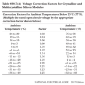
Bottom line... stop trying to find excuses to push your array voltage higher. Refer to this table:


1710190246215.png


If the record low in your area is 0°F, you need to allow an 18% temperature margin on your MPPT, i.e., multiply array Voc by 1.18. If it exceeds MPPT voltage, it's bad.

Alternative to the above table, you can run your own calculation using your panels' specific Voc temp coefficient.
 
Light gives voltage.
Intensity of light gives heat/amperage.

At sunrise, there is very little energy hitting the panels, but the light present is enough to nearly attain Voc, so heating will not significantly diminish the voltage. Even if this occurs for a fraction of a second, it may be long enough to blow the MPPT if Voc > MPPT max.


Important to be specific. "Rated" voltage may refer to Vmp as that's the voltage when the panel produces rated power. Voc is typically 20% higher than Vmp.


This will be true, but it can't be counted on. The reality is also that the MPPT will likely attempt to start pulling current to produce power. It's when reality is at the edges, such as low temperature charge protection is active, and the battery refused to accept current, so the MPPT can't pull the voltage down.

A very cold windy day with intermittent clouds can actually keep your panels at ambient temperature AND cause a concentration of solar larger than normal (cloud edging). Voltage and current are near instantaneous, but heating is much slower.

Bottom line... stop trying to find excuses to push your array voltage higher. Refer to this table:


View attachment 201555


If the record low in your area is 0°F, you need to allow an 18% temperature margin on your MPPT, i.e., multiply array Voc by 1.18. If it exceeds MPPT voltage, it's bad.

Alternative to the above table, you can run your own calculation using your panels' specific Voc temp coefficient.
Wow, that's good to know, thank you.

So, to be safe, when setting up a system, use the highest values on the panels, regarding voltage and amperage?

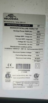
In the photo below, is the Voc temp coefficient the value "Tolerance: 0/+3%?"

I was referring to Zero Celsius, that's about as cold as it gets here in the winter, or maybe a few degrees colder at night, but that's rare.

Do I need to also account for an increase in amperage from the panels when it's very hot? In the summer it sometimes gets as high as about 45*C air temperature, and of course there is intense sun light for many hours on top of that. I see the specs on charge controllers also say a max input amperage.

Should I also factor in changes in voltage and amperage over the conductor length between the panels and charge controller. Mine is probably around 120ft currently. I also plan to add more arrays later this year with new/different panels, and some will probably be even further away. My understanding is voltage decreases over distance, while amperage increases. Does it work the same with the power going from the panels to the charge controller?
Solar panels.jpg
 
Wow, that's good to know, thank you.

So, to be safe, when setting up a system, use the highest values on the panels, regarding voltage and amperage?

Nominal Voc and Isc.

In the photo below, is the Voc temp coefficient the value "Tolerance: 0/+3%?"

That likely applies only to power.

I was referring to Zero Celsius, that's about as cold as it gets here in the winter, or maybe a few degrees colder at night, but that's rare.

I understand. It's important to do a deep dive and look at historical record lows as well.

Do I need to also account for an increase in amperage from the panels when it's very hot? In the summer it sometimes gets as high as about 45*C air temperature, and of course there is intense sun light for many hours on top of that. I see the specs on charge controllers also say a max input amperage.

I personally don't. I don't know if there's a code requirement. To get rated Isc (8.67A), you need 1000W/m^w falling on the panel surface. That doesn't happen all that often, AND that happens during short circuit. Current will usually be under Imp (8.12A). The 3% really doesn't matter at that point.

Should I also factor in changes in voltage and amperage over the conductor length between the panels and charge controller. Mine is probably around 120ft currently.

No. You only lose voltage when current is actually flowing. The current flow needed to accurately measure Voc is in micro/milliamps, so it doesn't affect Voc.

It will affect operating voltage. Operating voltage will be lower based on panel rated Vmp, current, wire gauge and distance. There will be a % voltage drop, and that will manifest as a like for like power loss, i.e., if you lose 3% voltage due to wire losses, you lose 3% power.

I also plan to add more arrays later this year with new/different panels, and some will probably be even further away. My understanding is voltage decreases over distance, while amperage increases.

This is true in the case of a 200W power supply powering a 100W load (you have a surplus of power compared to the load), i.e., you are pulling 100W @ 12V resulting at 100W/12V = 8.33A. If a long wire run causes the voltage to drop to 11V, the power supply will provide 100W/11V = 9.09A.

Note that if you only use a 100W power supply for the 100W load, and the resistance causes the voltage to drop to 11V, it will only be able to provide 11 * 8.33A = 91.6W to the load, which may not work. It's still providing 100W at its output terminals, but only 91.6W is reaching the load. The 8.4W is lost in heating the wires.

This is not the case with PV as they are more analogous to the maxed out power supply example above. Panels can't put out more than Imp. You lose voltage over distance. Current doesn't change.

Does it work the same with the power going from the panels to the charge controller?

No. Wiring losses are losses. Per above, if your wiring is causing losses, you are losing that power to heating the wires.
 
Nominal Voc and Isc.


That likely applies only to power.


I understand. It's important to do a deep dive and look at historical record lows as well.


I personally don't. I don't know if there's a code requirement. To get rated Isc (8.67A), you need 1000W/m^w falling on the panel surface. That doesn't happen all that often, AND that happens during short circuit. Current will usually be under Imp (8.12A). The 3% really doesn't matter at that point.


No. You only lose voltage when current is actually flowing. The current flow needed to accurately measure Voc is in micro/milliamps, so it doesn't affect Voc.

It will affect operating voltage. Operating voltage will be lower based on panel rated Vmp, current, wire gauge and distance. There will be a % voltage drop, and that will manifest as a like for like power loss, i.e., if you lose 3% voltage due to wire losses, you lose 3% power.


This is true in the case of a 200W power supply powering a 100W load (you have a surplus of power compared to the load), i.e., you are pulling 100W @ 12V resulting at 100W/12V = 8.33A. If a long wire run causes the voltage to drop to 11V, the power supply will provide 100W/11V = 9.09A.

Note that if you only use a 100W power supply for the 100W load, and the resistance causes the voltage to drop to 11V, it will only be able to provide 11 * 8.33A = 91.6W to the load, which may not work. It's still providing 100W at its output terminals, but only 91.6W is reaching the load. The 8.4W is lost in heating the wires.

This is not the case with PV as they are more analogous to the maxed out power supply example above. Panels can't put out more than Imp. You lose voltage over distance. Current doesn't change.


No. Wiring losses are losses. Per above, if your wiring is causing losses, you are losing that power to heating the wires.
Thank you, I think I understand it. I'm looking at probably replacing my system with Victron stuff, probably going to get the SmartSolar MPPT RS 450/200. It says max input voltage of 450V, so wiring up for 374V max, with a max low temperature at say -5*C would be a max of input of about 419V. Plenty of room there, right?

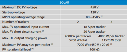
The spec sheet also says Max. PV operational input current: 18A per tracker and Max. PV short circuit current: 20A per tracker. So, using my same panels, I could put ten in series and then parallel two of those strings to go into one tracker (to use less wiring) which would equal 16.24A Impp (needs to stay below 18) and 17.34A Isc (needs to stay below 20). Even with calculating possible temp changes, I still should be more than an Ampere under the max allowable input, so I should be ok to do that, right?

Could I and should I put breakers between the solar panels to limit the input voltage and amperage to protect the solar charge controller? I have them now, but will have to change them out for the new system, because they're way too low on the voltage, however they're not really the limiting factor on my current system. I'm not seeing a 450V and 18 or lower Amp breaker. Just 400V then 500V. If I get the 400V breaker, I imagine it may trip often during the winter. If I get the 500V, it wouldn't prevent the controller from possibly ever getting damaged. Would I be forced to put only 9 panels in series to keep max possible voltage under 400V and then use 400V breakers to ensure the controller is never damaged?
 
Thank you, I think I understand it. I'm looking at probably replacing my system with Victron stuff, probably going to get the SmartSolar MPPT RS 450/200. It says max input voltage of 450V, so wiring up for 374V max, with a max low temperature at say -5*C would be a max of input of about 419V. Plenty of room there, right?

If 374V is Voc, yes. If it's Vmp, no.

The spec sheet also says Max. PV operational input current: 18A per tracker and Max. PV short circuit current: 20A per tracker. So, using my same panels, I could put ten in series and then parallel two of those strings to go into one tracker (to use less wiring) which would equal 16.24A Impp (needs to stay below 18) and 17.34A Isc (needs to stay below 20). Even with calculating possible temp changes, I still should be more than an Ampere under the max allowable input, so I should be ok to do that, right?

18A is the maximum current the MPPT can draw from the array. Note that there are 4 trackers in the /200.
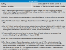
20A is the maximum Isc that the unit can provide reverse polarity protection, i.e., if you hook your panels up backwards, as long as no more than 20A is available, the unit will protect itself. If over 20A, the relays that short the array leads together to protect the unit will fail.
If you don't hook your array up backwards, the unit can handle 30A.

Datasheet:

1710220404784.png

1710220489230.png

Manual:


1710220559603.png

Could I and should I put breakers between the solar panels to limit the input voltage and amperage to protect the solar charge controller?

The only way to protect against voltage is to never have the possibility of exceeding 450V in any case.

Breakers are only REQUIRED if you have more than two strings in parallel. They may certainly be installed for convenience as a cut off switch.

I have them now, but will have to change them out for the new system, because they're way too low on the voltage, however they're not really the limiting factor on my current system. I'm not seeing a 450V and 18 or lower Amp breaker. Just 400V then 500V. If I get the 400V breaker, I imagine it may trip often during the winter. If I get the 500V, it wouldn't prevent the controller from possibly ever getting damaged.

Breakers are CURRENT protection devices, not voltage. Breakers do not protect against voltage. Breaker rated voltage is the maximum DC voltage they can reliably operate. If you install a 400VDC breaker on a 500VDC circuit, the breaker will fail to operate in the event of an over current situation.

The rated current of the breaker should be 1.25X the wire rating.

Would I be forced to put only 9 panels in series to keep max possible voltage under 400V and then use 400V breakers to ensure the controller is never damaged?

Hopefully, you can answer this yourself now.
 

Attachments

  • 1710220659194.png
    1710220659194.png
    107.6 KB · Views: 1
Back
Top