diy solar

diy solar

Why cheap BMS controllers can't do high currents

robaroni

New Member
Joined
Sep 30, 2019
Messages
35
If you're buying BMS controllers from China and are disappointed as to why claims of higher currents fall short this should help give you some perspective.

The problem lies in thin wires supplied, you can't have an AWG 22 wire controlling high currents (over a few hundred mA). It's not that the wire won't carry the current it's that the voltage drop is throwing off the readings the uC (microcontroller) or the comparator sees.

Here's what happens, let's say you want to charge a LiFeP04 battery to 3.65V and shunt the battery when it reaches that voltage with 1.5 amps. Let's also say the sense wire which becomes the shunt wire is 22 AWG. 22 AWG has a resistance of ~142 ohms per 1,000 feet or 0.142 ohms per foot. Now lets say the wires running to the batteries is 18" (1.5 feet) each battery wire. That means that by ohms law Voltage=current x resistance (E=IR) the voltage drop when the battery is shunting is E = 1.5 x (1.5 x 0.142) = 0.32V. This is the voltage drop across the wires. So when the battery is in shunt mode the comparator or uC sees less.

The comparator that is trying to shunt the battery at 3.65 volts now sees 3.65V - 0.32 = 3.33 volts. Comparator circuits have an aspect called "hysteresis". Let's say you want to turn on a shunt to stop charging at 3.65V. If you turn on the shunt at 3.65V you can't turn it off at 3.65V too, you would would get high frequency oscillations because the circuit would work against itself turning off and on simultaneously. Enter hysteresis - what you do is turn on the circuit at one voltage and off at another lower voltage, this difference is called hysteresis. So, say, when the battery drops to 3.60 volts the shunt turns off - except our circuit has dropped to 3.3V due to the loss in the 22 AWG wire China supplied. What you have to do is fudge the circuit, you can change things to compensate but it really doesn't work well. This is why you see higher quality high current circuits directly across the battery. They avoid this mess.

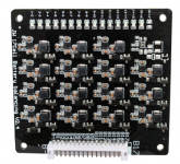
These are the types of BMS controllers you want.
Rob
 
Sorry, but all of your assumptions and conclusions are wrong. 22AWG wires are for cell voltage sensing, not for carrying current and have nothing to do with BMS current ratings. BMS does not shunt and sense at the same time, it uses time multiplexing to temporarily turn off shunting when it needs to sense voltage. Also, no one designs a BMS with 1.5A shunting and uses 22AWG wires. Most BMS's shunt at fraction of an Amp, as you don't need more than that on a healthy battery.
Now, the real reason for poor BMS current rating is a lot more trivial. Not related to balancing or shunting at all. BMS's primary function is to pass battery current thru a switching device, so it can turn it on/off to protect the battery when needed.
These small BMS boards use just a few small power MOSFETs as their main switching device. To keep the price low they use cheapest possible MOSFETs, which have relatively high RDSon spec, which is resistance in open state, which creates a lot of heat when passing high current. Datasheets for MOSFETs state max current at room temp, so these Chinese BMS's simply print combine ratings of their MOSFETs, but completely ignore the fact they don't have any decent heat sinking, so the current must be derated 3x-4x to prevent quick overheating and melting of these MOSFETs.
Well designed BMS takes into account the temperature rise and has appropriate heat sinking to keep the MOSFETs from melting and derates their max current based on temperature.

Not true, First you can't shut off a comparator to check cell voltage and some of these use comparators.

If you want a balancer with 50 or 60mA balance current these are fine but some claim higher current capabilities. Shutting off charging to test cell voltage doesn't work well because battery voltages need to settle before measurement - which means inaccuracies.

RDSon is no longer a factor in cheaper mosfets, you can purchase very cheap mosfets with RDSon in the milliohms.

A mosfet with an RDSon of 300 milliohms (high these days) at 1A has a power of i^2 * r or 300mW. That's nothing. I'm working with mosfets with RDSon of 3 and 4 milliohms. You can buy high quality 0.3 RDSon mosfets for pennies:


How is this ever going to accurately balance 1A per cell accurately?

https://www.aliexpress.com/item/32960521146.html
 
The title of your thread suggests you are referring to BMS main power circuit current rating, not shunt balancing rating. Maybe there is a confusion of the subject you are focusing on. Most people buy BMS for it's main power circuit rating, not for amount of balancing it can do, although it could be a factor in purchasing decision.

Plain analog comparator based BMS is a thing of the past, with many good multiplexing AFE chips on the market today. Even ShunBin batteries ( my measuring stick for simplest, cheapest possible BMS that can still be considered as workable solution ) came with a BMS based on specialized chip from BYD, you can see it in close up pics posted on this site.

That "thing" you linked from Aliexpress is a piece of garbage, not a BMS, so it's not really applicable in reasonable discussions.

That "thing" is exactly what I'm talking about and they still sell like hotcakes on eBay. I explained why they don't work. You seem to believe you can switch off a high current shunt and instantaneously measure battery voltage, you can't do that with any degree of accuracy and, again, you can't shut off a comparator to measure battery voltage at all.

And people do buy these "things" thinking they are going to shunt balance each battery in a string. I'm trying to help here, I was pretty clear about what I said and I tried to explain it in layman's terms so those without a background could understand and avoid mistakes.

Thanks for your input.
 
robaroni You bring up a good point. I'm currently hunting for a BMS for the system I'm assembling. I'll be keeping an eye out for absurdly scrawny leads. Thanks.
 
3S ~ 16S High Current Lithium Battery Balance Board 60V 48V 1.5A Current Balancing Active Equalizer Balancer Lifepo4 Lipo Li-ion


They're even screwing up the term "active" with regards to BMSes.
 
There are cheap BMS from china that do an admirable job. $22 US well constructed with plenty of Mosfets and waterproof maybe. Big leads for 60 amps out and higher .You are tarring all BMS with the same brush .
Spend your money as you please .
Mine will keep going into the cheap guys because I can afford to blow up 10 for the price of a 123 type system some suckers get fooled into buying.

At some point ,sooner probably,you will short a sense wire on a terminal while installing or maintaining and when you do that the board is RS. Another is required .

They all do a passive balancing of cells but as thats just burnt off as heat on the board it can't be much . Much better to wire in an active balancer thats also cheaply available now and feeds current from the high voltage cell to the low and they work very well. Again though currents cant be high due to heat not wanted.


Last edited:
Seems the Waters are Muddied on the various terminology used and understood. Much around Active & Passive balancing as well as capacities and how they are handled. Certainly can get confusing, especially when there is so much poorly translated advertisements & such which sure as hell don't help at all.

Some BMS's do active or passive balancing and use external relays to manage the high currents and shutoffs, some do it internally and are limited to capacities they can handle, which are usually lower amperages. Many include various cell monitoring functions, including hi & low volt & temp cutoffs and more features & functions. Of course Price goes with it too.

Case in point, I'm about to pull the trigger on a BMS Balancer system that uses external relays, has interactive management including RS232 communications out. Not a big expensive kit, a bit more than many but less than others with similar ability. This fits my particular application & configuration with my solar equipment & inverter/charger and how I want it to works for me. This is a key point, depending on what You want from a BMS and how it works, what it does & how for your purposes and uses.
http://chargery.com/BMS8T.asp

❗If your building something small with low amperage <100A there are many units like the Daly for example which should be fine for basic "pack" functionality (cell balancing, hi-lo & hi-temp cutoff). But be very aware that not all permit series or parallel connections of packs... RTFM ! that is if you can get a manual/docs.
If your building bigger packs to run a cabin/home or EV charging then more serious BMS systems that can handle high volts / high amps are needed for those packs. Simply look at the Bigger Name makers like OrionBMS or Battrium and the like and see how & what they do.

Great listing here on BMS info on products & companies, Cell/Battery Makers & tons more, a valuable resource, Even a BMS Selector ! :

EDIT : Tues. Dec.03
I just wated to addm in regards to Chargery Inc. I have emailed them with questions and wanting the interface docs for PC communications... response was fast & helpful and they sent along the docs too.... So this is what will take over the ShunBin Pack, which came with one of those ultra cheapo single board BMS's with the famous No-Name brand with unknown function / capability.
 
Last edited:
Egads. That's really lame. Thanks for the heads-up. We should all be asking that so the sellers get trained that that practice is not accepted.
 
It's true you can't measure cell voltage accurate during balancing with the same thin cables. One of the reasons I do not believe too much in BMS with balancing function.
My Daly 200A 16S BMS had only 30mA balancing and totally no effect. If there was really balancing electronics inside is hard to say because it cannot be opened, it has no leds and no monitoring.
Fortunately this BMS died after just plugging in the 16 pole cell connector 2 months ago. One more unreliable thing eliminated.

Still have 36 crap cells from BLS battery, varying from 170Ah to 200Ah in 2x16S, Keeping these cells 'in balance' as much as possible to get the maximum power is a weekly job, including charging and bleeding of some individual cells.

I was monitoring all cell voltages myself already, based on ESP32, and now I am trying a separate energy transfer balancer (1.5A) from Aliexpress (Broodio 16S ; 25$ ). Small, clever electronics with an IC for every cell.
I can really recommend it because it's actively balancing with enough current and it has a red led for every cell. That shows very clear which cells have more than 0.15V devation.
When bleeding or charging cells, just stop when the led goes out. Very easy.
Of course this unit needs an extra wire to every cell. There could be more units in parallel to enhance current.

To eliminate a cable nest above the cells, I use 30 cm 2.5mm wires from all cells to a terminal block outside the battery pack.
Every wire is fused close to the cell with a 15A fuse.
Connecting unfused thin wires directly to high power cells seems a high risk to me. That's what we do with all BMS, not knowing the electronics inside. If a short could happen inside then your wire may become a light bulb.

Reading accurate cell voltages is no problem during balancing since there is almost no loss on the 2.5mm cables and 1 A balancing current also has no short term effect on the cell voltage.

The PV input cables (120V - 10A) are much more of a concern on voltage readings even they are 40 cm away from my ADC channels and all data passes through I2C. They produce huge interference.

To eliminate high inrush currents to the inverter (every time a BMS turns back on), the ESP32 switch off the inverter by its powerbutton (with small relay) if cell voltage drops too far. It acts like a BMS but without the high inrush as the capacitors are always connected and charged.

When cell voltage goes above 3.6V I switch on/ off PV panel groups depending on the cell voltage but my inverter does not switch off as well like most BMS do. Silly to turn off the load when your battery is full.. A BMS with separate port should prevent that but my Daly switched off completely when the charge port got >35A. Just don't buy Daly, common port or separate port. Really.

Now I am free of cheap Chinese BMS worries. But still have bad BLS cells..
 

Attachments

  • 1576620595586.png
    1576620595586.png
    265.9 KB · Views: 17
Fortunately this BMS died after just plugging in the 16 pole cell connector 2 months ago. One more unreliable thing eliminated.
Im guessing it was not wired in properly if the truth be known. If one sense wire is off or has a bad or wrong connection then it just won't turn on until its wired right. I have not had a bad one or lost one yet and I'm up to 8 so far. But I know how you must feel because the 16s ones are $50 a piece and losing one would be very annoying especially when you have copped a load of bad cells too.

Another reason for separate strings ,each with a BMS. If a cell gets out of whack and turns the string off the other strings continue the work . What these BMSs do need is an LED to tell you the string is turned off.

Im finding the active balancers are doing the job nicely and there is a more expensive capacitor based thing out now so maybe someone will review it . I will do it if and when I have to build my next battery pack for my security system clients.

The passive balancing on most BMSs is just to give the other cells a chance to catch up . If you have a 20 amp charge running through the pack then if one cell starts feeding 50mA through a resistor you are not going to notice anything except maybe an increase in heat coming off. As you said a good idea to have an LED on that too when it turns on .
 
Last edited:
All this...is why I bottom balanced my cells and keep max charging voltage to 3.4v/cell or 13.6v for my 12v nominal pack. That and a low voltage disconnect and no worries about a cheaply made component starting a fire or trashing my battery.
 
All this...is why I bottom balanced my cells and keep max charging voltage to 3.4v/cell or 13.6v for my 12v nominal pack. That and a low voltage disconnect and no worries about a cheaply made component starting a fire or trashing my battery.
Mmm time will tell. Your pack can be at 13.6v but how will you know if one cell has lost capacity and sits at 50% while another is dangerously over 3.7V ?
And mate they don't catch fire so why would you need to employ a scare tactic to get your point across?
 
Im guessing it was not wired in properly if the truth be known. If one sense wire is off or has a bad or wrong connection then it just won't turn on until its wired right. I have not had a bad one or lost one yet and I'm up to 8 so far. But I know how you must feel because the 16s ones are $50 a piece and losing one would be very annoying especially when you have copped a load of bad cells too.
The wiring was ok, it worked 4 months already. The sensing wires connector is not often unplugged in normal situations but bcoz of my bad cells I had to replace cells sometimes with other spare cells to get the best possible match. In that case I had to disconnect the BMS connector first.
I have done that a few times without problems.

If I wouldn't have such bad cells I probably never have disconnected the BMS again and be happy with the Daly. But in times of trouble, you learn about your friends...or the quality of electronics.
Btw the 200A 16 S Daly costs me 115$, not 50$.

I will cut it open one of these days because I want to know what's inside.
 
Back
Top