Sean Steele
New Member
- Joined
- Aug 28, 2020
- Messages
- 95


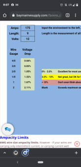
Voltage drop, got it.smoothJoey, I don't remember the exact chart now but I just clicked the link to bay marine in your first reply and entered my parameters. 2 AWG is at the bottom of the results but still <3% for voltage drop.
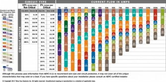
The ampacity tables are below.Are you saying I shouldn't use that reference for ampacity?
Pfft... for that, you would be fine with #8 wire...Biggest load that will run for extended periods is my tv and blu-ray player. Otherwise short bursts charging laptops and cell phones or long runs of a small fan.
ABYC and NEC ampacity charts are pretty well harmonized I think. Are you sure you are referencing tables for similar conditions and wire insulation temperature ratings?By the aybc chart I linked 1 awg is indicated.
4/0 by nec.
But ampacity is independent of length, yes? At a minimum the wire used must be off a high enough ampacity to handle the max continuous load, regardless of length. At least that is my understanding.the wires in the inverter can be small due to length..
Voltage drop, got it.
That is the baymarinesupply.com calculator, and I'm almost positive it accounts for both Voltage Drop and Ampacity.Are you saying I shouldn't use that reference for ampacity?

Nope.ABYC and NEC ampacity charts are pretty well harmonized I think. Are you sure you are referencing tables for similar conditions and wire insulation temperature ratings?
You are correct again, see above.That is the baymarinesupply.com calculator, and I'm almost positive it accounts for both Voltage Drop and Ampacity.
See, now this sounds backwards to me. I would think you would chose the wire to handle max amps and then fuse to protect the wire.The most important thing is to size the wiring to the fuse you intend to use. For 2000W, something around a 250A fuse is usually recommend, at which point most charts recommend 4/0, even for a short run.
I agree, except for special cases like this: Consider a 2000W inverter. The maximum continuous amps might be 190A, but the recommended fuse might be 250A. The run is short, so voltage drop is not an issue. How do you size the wire? My point is that in limited cases like this where there is a recommended fuse size, the process is inverted. Pun intendedSee, now this sounds backwards to me. I would think you would chose the wire to handle max amps and then fuse to protect the wire.
My inverter has a recommend wire size but no fuse size. Since I went with 2AWG which is supposed to be good for 210 Amps, I figured on installing a 200A fuse. Of course, this is contrary to the *1.25 rule that most apply for fuse headroom. My inverter is 2000W. It's surge rating is 4000 for 40 milliseconds. The circuit I am powering, built in ATS, is protected by a 15A breaker on the AC side and the inverters AC bypass is 2000W.Ok. So let's apply this to a 2000W inverter. The maximum continuous amps might be 190A, but the recommended fuse might be 250A. The run is short, so voltage drop is not an issue. How do you size the wire? My point is that in limited cases like this where there is a recommended fuse size, the process is inverted. Pun intended
What is the recommended wire size?My inverter has a recommend wire size but no fuse size.
40 milliseconds is ~2 cycles of 60hz alternating current and can therefore be ignored as insignificant.Since I went with 2AWG which is supposed to be good for 210 Amps, I figured on installing a 200A fuse. Of course, this is contrary to the *1.25 rule that most apply for fuse headroom. My inverter is 2000W. It's surge rating is 4000 for 40 milliseconds.
If you are ok with popping fuses from time to time you should be fineI'm fine with popping a fuse once in a while, I just want to make sure my wires and equipment are protected. Is my logic flawed?
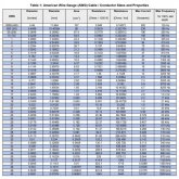
For 90dg C insulation, I'm seeing maximum 130A for #2 wire. For 60dg C insulation, it's only 90A. The attached charts may be conservative, but they have served me well, as a guide.My inverter has a recommend wire size but no fuse size. Since I went with 2AWG which is supposed to be good for 210 Amps, I figured on installing a 200A fuse. Of course, this is contrary to the *1.25 rule that most apply for fuse headroom. My inverter is 2000W. It's surge rating is 4000 for 40 milliseconds. The circuit I am powering, built in ATS, is protected by a 15A breaker on the AC side and the inverters AC bypass is 2000W.
My BMS is supposed to cut off at 175A output but we all know they go over that rating for a short time. The battery has an internal fuse of 300. With my meager understanding, 200A fuse protects the wire while still allowing for some surge, 2400watts. All of these watts are calculated at 12v but the battery will normally be operating between 13 and 14 so, slightly less amps to make the same Watts.
I'm fine with popping a fuse once in a while, I just want to make sure my wires and equipment are protected. Is my logic flawed?
"2AWG or larger"What is the recommended wire size?
The 2AWG I bought from BatteryCablesUSA is 105C.For 90dg C insulation, I'm seeing maximum 130A for #2 wire. For 60dg C insulation, it's only 90A. The attached charts may be conservative, but they have served me well, as a guide.