diy solar

diy solar

Wiring design (series/parallel) for thin layer 45V PV pannels 10 kw system

bigimot

New Member
Joined
Aug 15, 2020
Messages
5
Greetings from Bulgaria!

I'm totaly beguiner in this solar field, but this forum is great and I learn many new things here!

I bought some second hand thin layer PV pennels and want to made solar system for my house, mainly for the thermo pump heating in the cold months (from September to May here).

My plan is to use about 150 from those pannels (60x120 cm 65W max) with 2 ps of 5kw, 48V invertors in paralel + betteryes (I didn't decide which type to use yet).

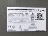
The problem that I face is the high PV output voltage of those pannels - 45V (please see the PV panel specc table attached). The inverters that I choose (not ordered yet) are the MPP Solar PIP 5048 MGX with max PV input of 450V and 5000W.

My idea is to connect 8 pannels in series for one string ( will be 360V at 45W )and then to use 9 such strings in parallel with final PV output of 360V at 405V from 72 pannels in total. having 2 indentical sets like this will receive about 8kw at 720V from 144 pannels and if this is spited by the 2 inverters should be fine?

What you think for this theory design? Will it work fine or I should try to get higher Voltage or Wats to the invertors?

Thanks in advance!
BR
Alexander
 

Attachments

  • specc PV panel.jpg
    specc PV panel.jpg
    61.5 KB · Views: 8
The thing you want to pay attention to is the Voc. The Voc of the array must never exceed the maximum voltage rating for the inverter. That means 450V for your 5048. I think the panel Voc is 51.9V (image isn't clear enough to tell). If you put 8 panels in series with that Voc you will reach 415.2V nominal. That's safely below the 450V limit for silicon panels, but I'm not familiar with your thin film panel so the effect of temperature isn't something I can pull off the top of my head.

Your configuration still works even though you've been working with Vmp. You'd build two separate arrays consisting of 8s9p and connect each array to one of the PV inputs on the 5048. The standard warnings about fusing still apply. When you have more than 2 strings in parallel you should place a fuse between each string and the common + wire. The strings will only produce 1.82A shorted so if anything you may find it difficult to get fuses rated low enough given most people work with higher current silicon panels.

*edit*

Apparently they have a lower temperature derate, -0.24%, than silicon so that Voc should be fine.

Just noticed you intend to use two 5048 inverters and parallel their outputs. TBH I'm not familiar enough with the 5048 but I do know they have two separate PV inputs. If you use two of them you'd probably be breaking down your 8s9p arrays and rearranging them so you can spread them evenly across both 5048's inputs. Maybe 8s4p, ie 8 panels in series still but instead of 9 parallel of those, only 4 parallel and put each of those 8s4p arrays on one PV input of the 5048. You could soak up the 16 panels that would leave separate from your 144 configuration by putting 8s5p on two inputs. Gets messy with this many low current panels.

Inverter 1
port a: 8s4p
port b: 8s5p

Inverter 2
port a: 8s4p
port b: 8s5p
 
Last edited:
Thank you for the answer gnubie!

Abou the panels specc. they seams to have some difference from panel to panel. Here is another panel label attached with Voc 59.1V. This incease the voltage in the calculation even more.

About the inverer, should i search for a models with higher PV V input? I found one model of EA Sun in Ali express with 500 V PV input. This is 50 V more than 5048 model.

https://www.aliexpress.com/item/400...earchweb0_0,searchweb201602_,searchweb201603_

About the fuses. This is part of the manual (I add it as file here too) for those panels. They give 2 options - to use diodes or fuses on the strings - and + parts

1599305890959.png
1599305919915.png

I didn't search yet for sutable fuses too.

About the 2 PV input port of the 5048. I will check that.
 

Attachments

  • 5.jpg
    5.jpg
    80.8 KB · Views: 2
  • OperatingManual.pdf
    1.1 MB · Views: 1
I would stick with the MPP inverter rather than something off aliexpress. The MPP isn't top shelf but it is a known quantity and has proven itself to work well enough.

You can use diodes to prevent a faulty string being backfed but diodes can fail shorted so you should have the fuses too. Fuses mandatory, blocking diodes optional. A blocking diode(s) will prevent a failed string from drawing current at all so that can be an advantage by allowing the full power of the remaining working strings to be available rather than going into heating up the failed string.

I'm not sure why they recommend a fuse on both the + and - side of the panel though. That might be related to the construction of the thin film panel but I don't know enough about them to say for sure.
 
They look like they should do the job. Does the fuse holder include the fuse? How do you plan on joining the parallel sets - DIY or pre-made cables or would you considered the combiner box path? Combiner boxes can have a fuse per string so that'd cover you for the fuse at one end of the string, if you are going for fuses at both ends as per the manual.

I know the list of things you need to consider keeps growing but joining it all up has to happen at some stage. Normally people use a combiner box when doing several strings in parallel as it includes fusing, isolation breakers etc, but with all the panels you have that's going to add up to a reasonable amount of money.
 
Last edited:
Just have a talk with a friend of mine, who was made solar systems as job before some time. He told me, that in my case the easyest way will be to made a box with diodes and brekares which will cover each part of the strings. Then from this box mest have stronger wires to the inverters. He also told me, that because of the higher voltage of the pannels will be good to use 2 diodes in series instead of just one.
 
Back
Top