diy solar

diy solar

Wiring out of Charge Controller

MountainmanBill

New Member
Joined
Feb 20, 2021
Messages
69
I'm a bit confused, as I am with most things solar, where to go with the wiring out of the two MorningStar TriStar MPPT-45 (150 volt) charge controllers. I have two positive and two negative wires from the bus bars in the combiner box going to the two charge controllers. I can only assume that the positive and negative wires coming out of the CC's go to the 48-volt battery bank, and off the battery to the inverter. If that is indeed correct, where on the many battery posts to choose from do I connect the wires to? There is a post and a stud for each positive and negative of the 8, 6-volt batteries connected in series. A total of 32 locations to choose from. Does it matter to which post or stud I connect the wires to from the CC to the battery, and from the battery to the inverter?
 
From what I can understand from your question. Yes it matters. Voltage adds up for each battery you have in series and you want to make sure you are charging all 48Volts. You want to connect the CC to the first and last battery in the string of batteries and to the appropriate sign (-/+). The
MorningStar TriStar MPPT-45 (150 volt) works with "12, 24 and 48 Volt dc systems" so you want to make sure that it's connected to the battery bank as a 48V system.


I used 12V battery to simplify the diagram, but the information is very similar.
 

Attachments

  • battery strings.png
    battery strings.png
    98.3 KB · Views: 6
Ok, well that would take care of one charge controller, where do I connect the other? To the same posts as the first controller? And do I also use those same posts to go to the inverter? In other words, do I connect both charge controllers and the inverter to the same posts on the battery bank? Three positive wires on the first positive battery post and three negative wires on the last negative battery post?
 
I haven't worked with this model yet, but yes. You typically can connect them all to the same post or a DC bus, (if your system has one). The order that you connect to the post is important. It depends on wire sizes and hardware. The conductor with the highest potential of current (usually means the larger conductor) should sit the closest to the batteries and then descend by wire size (which relates to current rating).

Does that help? I can give you a better drawing/depiction, if you'd like.

Are you planning to have some circuit breaker or ability to isolate your batteries?
 

Attachments

  • ordermatters.png
    ordermatters.png
    38.2 KB · Views: 11
That helps a great deal Ma'am. I thank you for that!

If it's a good idea to isolate the batteries I shall do so. And how would I do that again? :)

The panel wiring has breakers, but nothing after that, and only because I don't know any better. I'll put in anything and everything that is necessary. All I need is a little guidance.
 
Last edited:
speaking of charge controllers, this device sits between the battery and PV panels right (since it has to have a way to "control" the "charge" to the battery)? How does the controller deal with the PV array giving more power than the battery (and house loads) can handle?
 
speaking of charge controllers, this device sits between the battery and PV panels right (since it has to have a way to "control" the "charge" to the battery)? How does the controller deal with the PV array giving more power than the battery (and house loads) can handle?
The load will try to draw what ever the power is needed from the system, if no load then there will be very current draw from the system. Just think about it for example yur house AC outlet that can supply 120VAC up to 15A, if you have nothing connected to it there willl be no current flow even though the outlet can supply 1800W of power.
If the battery is fully charged and no load connected to the system, the circuit will ony draw just enough current to run the micro controller and display.
Also if you over panel the system, the SCC will throtter down the power to its maximum limit per spec.
 
It is best to have some type of protection and ability to isolate energy sources. You can use circuit breakers to do this. This means at the battery, after or before the charge controllers on the DC side.
 
Well then, with that advice...
If I trip the breakers at the combiner box, I would be shutting down current to the charge controllers and in turn to the batteries. If I install a breaker between the battery bank and inverter, I would be completely isolating the battery bank. No power charging the batteries and no load being applied to it. Sound right?

What size breaker in that position? Does that depend on the load from the inverter? If so, what’s the math to find out?

And thank you paul12345 for the link. It was indeed helpful...
Is the inverter your only dc load? What size inverter?
 
Whoops, sorry. 48-volt 4000 watt. The inverter will be yawning most of the time as I won’t be putting much of a load on it, at least for now. A 400 watt fridge and a 535 watt window AC unit and a few other incidentals not worth mentioning. Maybe a thousand watts running wattage.

I assume too that out of the inverter I need to set up a breaker panel to service three or four outlets? Yes?
 
Whoops, sorry. 48-volt 4000 watt. The inverter will be yawning most of the time as I won’t be putting much of a load on it, at least for now. A 400 watt fridge and a 535 watt window AC unit and a few other incidentals not worth mentioning. Maybe a thousand watts running wattage.
4000w/48v = 83.3 amps not including surge capacity. I’m assuming this is a low frequency inverter and you should calculate that. if surge capacity is 3x, then 4000x3 = 12000/48 = 250a x 1.25 = 312.5a this is over sizing. You could get away with less as that max surge would likely be less than 100ms. For industrial they will allow their capacity to be surpassed for 5 10 30 minutes respectively at different overload values. Your wiring needs to be able to sustain those maxes if you plan on hitting them. once you decide the wire size you want to use, then fuse it with the appropriate size fuse for that wire’s ampacity.

I assume too that out of the inverter I need to set up a breaker panel to service three or four outlets? Yes?
I would, yes.
 
Well then, with that advice...
If I trip the breakers at the combiner box, I would be shutting down current to the charge controllers and in turn to the batteries. If I install a breaker between the battery bank and inverter, I would be completely isolating the battery bank. No power charging the batteries and no load being applied to it. Sound right?

What size breaker in that position? Does that depend on the load from the inverter? If so, what’s the math to find out?

And thank you paul12345 for the link. It was indeed helpful...

This article might help you as well.

 
There has been some deviation from the original query, which I am happy for, and as long as it has, I'd like to continue my knowledge quest for isolating the battery bank, it's fusing, and the appropriate wiring thereof.

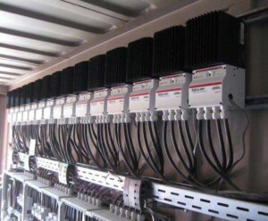
I got my MidNite Solar Combiner Box yesterday and the installation instructions states an interesting fact pertaining to fusing. Specifically referring to out of the Charge Controller(s). "...and out of the controller to an output breaker. The main job of this output breaker is to trip when and if there is a catastrophic failure. When a charge controller fails, they always short from positive output to negative output. Since these two terminals inside the charge controller are normally connected to a very large battery bank, you have a direct short across the battery bank if the controller fails. During this condition, the controller is acting like a piece of wire. The battery positive terminal is the highest potential! Make sure that the plus (line) of the breaker is connected to the battery plus terminal. If the breaker is connected backwards, it can fuse in the closed position as it attempts to open. That could ruin your day!" It goes on to say, referring to fuses (breakers), that "These devices are not polarity sensitive, but do not open them under load. You WILL have a fire on your hands!"

The latter is an interesting fact that I'm glad I learned about. The former tells me that I should install a breaker after the charge controllers, not after the battery bank as I first assumed. Because, if I interpret the information correctly, in the event of a not-very-common catastrophic failure of the charge controller, it could take out my battery bank, or perhaps worse.

With that said, there's still the question of the size of the breakers between the charge controllers and the battery bank. In another thread of mine it has been determined that the 2 charge controllers will will feed the battery bank "60 amps @ 50 something volts". But since I have differing voltages and amps for each controller, I would need to figure out the separate output amps of each charge controller, multiply the max output amps by 1.5 and use that size breaker, correct? Do I have that right?

As far as other breakers in the system, I should be getting my inverter sometime next week. I'm hoping the information enclosed within will shed some light on that. Thank you all again for the help. This is a wonderful forum with wonderful people whose knowledge is invaluable!
 
Like any other electrical system, battery systems must have proper DC-rated overcurrent protection and disconnects to protect system conductors and to isolate the battery bank from the rest of the system to testing and/or maintenance. Batteries can deliver extremely high discharge currents, so overcurrent protection devices are important. It should have a current limiting overcurrent protection with an especially high interrupt rating.


Circuit breakers are there to protect the conductors. So that the CB trips instead of the wire possibly burning in an overcurrent case, keep that in mind. The overcurrent device rating should be no less than 125% X the DC/DC converter (CC) continuous output.

The systems I have worked with had a CB at the batteries and at the CC. I don't think the statement above says not to have protection at the battery but emphasizes having protection at the CC.
 
Back
Top