diy solar

diy solar

YamBMS JK-BMS-CAN with new Cut-Off Charging Logic (open-source)

I'll digest your post more later, but I am curious at how you have a cell that exceeds OVPR if using charge current control.
If a cell hits OVPR then current will be 0, and the cell voltage shouldn't rise further. Indeed, the balancer should start to pull it back.

Additionally, the code used on the ESP32 has div0 handling, so won't be affected by that issue you raised. I'll adjust the spreadsheet at some point.
Because I was trying to simulate what would happen if we don't lower the charger voltage slighly below the battery pack voltage. Basically trying to simulate this 54.3V or 54.4V which is the pack voltage... I can still see the inverter "pulsing" some 300W or so (5A) as said before into the battery. So that's not something the balancer had time to counteract.

It would NOT necessarily discharge the battery. Of course unless a cloud would hit the solar array at that very moment 🤣.

But, just like you INCREASE the charge voltage above the battery pack voltage in case ALL cells are below 3.45VDC, you should DECREASE the charge voltage below the battery pack voltage if ANY cells are above 3.45VDC. The higher the difference to 3.45V and the more cells are going high, the more you need to LOWER the charge voltage BELOW the battery pack voltage.

It's effectively like trying to push current through a diode... If your voltage isn't 0.7... 1.8V higher, no current will flow.

The same we should achieve here. If any cell went too high, the algorithm should promptly reduce the charge voltage to give a chance to the balancer to catch up.
 
Looking at your screenshot as below:
View attachment 204085
As you can see, the requested charge voltage is essentially the same as current battery voltage. If your inverter respects CVL correctly, the current going into the battery should approach zero, allowing time for the balancer to pull the max cell back.

This approach doesn't apply a penalty that reduces CVL below actual battery voltage. That approach would work to discharge the battery (with some inverters) though, giving even more opportunity for the balancer to fix the issue.

The alternative approach of applying voltage penalties per cell if they exceed a threshold is definitely possible. I haven't tested that method with my setup however, as my inverter will not discharge the battery when CVL is lower than actual battery voltage.

Thanks for digging through this and providing comments, there's always room to refine and improve!
You're welcome.

It's just important in my view to apply a negative bias to the charge voltage whenever a cell is starting to get too high (>3.45vdc).

There are other analogies that might help explain it better, in case you cannot fully follow my Argumentation:
- When you want to block an IGBT, you don't only set 0V on the gate, you apply a negative voltage (-8V for instance) to avoid spontaneous / parasitic turn on
- When you want to slow down a motor (electrical braking), you effectively operate it as a generator (DC motor for simplicity: you apply a negative voltage)
- When you want to forge current to zero, you apply a negative di/dt i.e. À négative voltage (That's why arc voltage of fuses are like 3-4 x system voltage, why arc voltage of breakers are like 2x system voltage for instance)

From a mathematical standpoint, it's very similar to the issue of using coulomb counting to estimate the remaining capacity / SOC of the battery, except it's for real here. If the inverter is set to a given charge voltage of say 54.4V and you only have like <5 mOhm of resistance including cabling, à measurement uncertainty of 50mV is already enough to let 10A flow.

As soon as the cell is getting discharged by the balancer, the inverter will recharge the battery pack.

The difference being:
- balancer discharge in current control mode, say fixed 2a, until the supercapacitor are charged to the required level
- inverter recharges in voltage control mode, so the current flowing will simply be ( inverter voltage - battery voltage) / ESR

Now... It's a bit late here so please correct me if wrong...

For a given energy capacity of the JK BMS balancer supercapacitor:
- At the high state of charge, the balancer discharges that same amount of energy and the voltage reduces a lot (im relative terms)
- At the low state of charge, the balancer charges the same among of energy into another cell and the voltage changes a tiny bit only

This means that as soon as one cycle of balance I completed, basically we are right back where we started.

Slightly better, since now that the other cells raised a bit in voltage, the inverter will not push as much energy back as it was balanced. But it's like 99% of the balancing was for nothing.


But compare this to having the inverter stopping delivering power altogether and let the balancer do it's job. I staged before my experience... 180s to let the balancer do it's job, if inverter is not recharging.

And previous experience with a manually controlled staircase voltage ramp up showed top balance achieved in 36 hours!!!
 
Because I was trying to simulate what would happen if we don't lower the charger voltage slighly below the battery pack voltage. Basically trying to simulate this 54.3V or 54.4V which is the pack voltage... I can still see the inverter "pulsing" some 300W or so (5A) as said before into the battery. So that's not something the balancer had time to counteract.

It would NOT necessarily discharge the battery. Of course unless a cloud would hit the solar array at that very moment 🤣.

But, just like you INCREASE the charge voltage above the battery pack voltage in case ALL cells are below 3.45VDC, you should DECREASE the charge voltage below the battery pack voltage if ANY cells are above 3.45VDC. The higher the difference to 3.45V and the more cells are going high, the more you need to LOWER the charge voltage BELOW the battery pack voltage.

It's effectively like trying to push current through a diode... If your voltage isn't 0.7... 1.8V higher, no current will flow.

The same we should achieve here. If any cell went too high, the algorithm should promptly reduce the charge voltage to give a chance to the balancer to catch up.
I might be missing something, but if the requested charge voltage is 54.4v (as a cell is over the 3.45v target) and your battery is also at 54.4v, the resulting current flow would be zero, wouldn't it?
That's meeting your requirement of reducing the current in order to allow the balancer to work.

The current control logic is there to prevent UVP and OVP, but not to limit a cell to no more than the desired voltage. It's basically a 'safety net' for misbehaving battery packs.

You say that you 'see the inverter "pulsing" some 300W or so (5A) as said before into the battery'. Does that happen even when your CVL is the same as the battery voltage?
 
I see our replies crossed over at the exact same time!
I understand your rationale, particularly when referring to measurement uncertainty - assuming that the values from the BMS are perfect and there's no external factors, we would have no issue.
But, as you say, if things are a little less than perfect then we have scope for current flow over what we desire.
I'm not married to this logic by any means, so perhaps we should collaborate on v2 logic. Building in leeway for non-perfect situations makes a lot of sense.
 
I might be missing something, but if the requested charge voltage is 54.4v (as a cell is over the 3.45v target) and your battery is also at 54.4v, the resulting current flow would be zero, wouldn't it?
That's meeting your requirement of reducing the current in order to allow the balancer to work.

The current control logic is there to prevent UVP and OVP, but not to limit a cell to no more than the desired voltage. It's basically a 'safety net' for misbehaving battery packs.

You say that you 'see the inverter "pulsing" some 300W or so (5A) as said before into the battery'. Does that happen even when your CVL is the same as the battery voltage?
In a perfect world it should be enough. I'm not blaming you for questioning that 😉.

The 300W or 5A is also a bit difficult to explain... It's not necessarily "pulsing" but... Kinda.

I don't necessarily trust the JK BMS voltage measurement 100%.it might show 54.28 V while the inverter is probably doing float at 54.3 vdc and the other bms reports 54.34V or something like that.

So it might be slighly higher voltage on the inverter side, or just long-term equalizing effect taking place between parallèles batteries.

The other case of non ideal behavior would be a load step. In my case (off grid) if I suddenly turn off a big load, I would expect some transients in the battery current.

I'd say this is much more pronounced during discharge and near UVP, but you don't want a sudden load jump near UVP causing your cell to hit UVP and losing your battery source (if you are off grid).
 
I see our replies crossed over at the exact same time!
I understand your rationale, particularly when referring to measurement uncertainty - assuming that the values from the BMS are perfect and there's no external factors, we would have no issue.
But, as you say, if things are a little less than perfect then we have scope for current flow over what we desire.
I'm not married to this logic by any means, so perhaps we should collaborate on v2 logic. Building in leeway for non-perfect situations makes a lot of sense.
And our messages crossed again 🤣.


The easy quick fix (for now) would be to introduce a negative voltage offset parameter of say - 0.2v for the whole pack but only if one cell is above 3.45v.

Or habe some PI controller or similar as well.

I'm just a bit concerned that it won't work for me as it is now. I just got the CAN hat and could run some tests tomorrow most likely. But I still think I will need to manually intervene to lower the charge voltage below the battery voltage, in case one cell misbehaves badly.

I think the algorithm is interesting, but it seems very unidirectional in what it's tackling.

My approach would rather be: first of all, stop the bleeding, give that balancer some time to do it's job. Then raise the voltage slowly again if cell is again below 3.45V.
 
@MrPablo : for the tolerance on the voltage you actually have 2 things to consider
- jk bms voltage offset / error
- inverter voltage offset / error
(I though you already had one offset parameter in the yaml configuration, just not for this particular issue)

Plus possibly ADC température compensation lacking / doing differently. Yes, we are not doing ppm level accuracy, but given the small ESR between inverter and battery, not many volts can do lots of amps and joules 😉.
 
Just found a corner case (I'm good at finding those :ROFLMAO: ) - if you put the cell #01 at 3.45V it throws an error:
View attachment 204035


I downloaded the spreadsheet as ods from Google Docs since Firefox is basically hanging ...

In Libreoffice Calc (since I only use GNU/Linux)
View attachment 204049

To me it seems like it's *NOWHERE* nearly aggressive enough. These are actual cell voltages I sometimes saw ...
View attachment 204041


View attachment 204044


(today there wasn't so much sun so it didn't hit 3.55VDC which is my OVP - OVPR set at 3.50VDC. Yesterday it hit 3.55VDC while all other cells were around 3.38VDC-3.39VDC)

I can easily hit OVP at 54.4 VDC. 54.3VDC "maybe" (like today it was OK, depending on sun irradiance).

EDIT 1: Fixed OVPR to 3.50VDC (was wrongly set in the screenshot of Spreadsheet to 3.55VDC).

EDIT 2: the "Algorithm Sensitivity (lower = aggressive)" doesn't seem to do much.

EDIT 3: Maybe the Charge Voltage Algorithm can work sufficiently well in conjuction with the Charge Current Algorithm, but the latter needs to be super aggressive as well
View attachment 204051


EDIT 4: The basic principle is that it will limit the charge voltage to the actual / current battery voltage (unless there is "headroom" to charge more, i.e. all cells are below the knee point of 3.45VDC). I just wish we could add some offset (-0.2VDC ?) in the cell goes above 3.45 VDC (because believe me, if the inverter keeps pulsing 300W or so (5A) into the battery bank, the 2A balancer of the JK BMS for sure cannot keep up ...

EDIT 5: This is also the case because, when the active balancer is trying to discharge the highest cell, it effectively creates a "charge pump", i.e. the inverter will forcefully recharge the highest cell as soon as the voltage (of that cell / that battery) drops. The only thing to avoid this is to set the inverter voltage *slighly* (e.g. -0.2VDC) lower than the pack voltage. So it's a kind of "ad-hoc" float effectively, until the voltage can ramp up (slowly) again, once the balancer of the JK BMS did its job.
Have to go to all your very detailed infos the next days - thx for sharing :)

But can you also share your bms config please? for me it does not look like a normal behavour that one cell is peaking every day
just want to be shure - from my perspective, there is not optimal configurated BMS setup or a bad/not matching cell in that pack

what is your COVP, COVPR, Balance delta trigger and balance starting voltage?
 
Last edited:
And our messages crossed again 🤣.


The easy quick fix (for now) would be to introduce a negative voltage offset parameter of say - 0.2v for the whole pack but only if one cell is above 3.45v.

Or habe some PI controller or similar as well.

I'm just a bit concerned that it won't work for me as it is now. I just got the CAN hat and could run some tests tomorrow most likely. But I still think I will need to manually intervene to lower the charge voltage below the battery voltage, in case one cell misbehaves badly.

I think the algorithm is interesting, but it seems very unidirectional in what it's tackling.

My approach would rather be: first of all, stop the bleeding, give that balancer some time to do it's job. Then raise the voltage slowly again if cell is again below 3.45V.
I would like to redesign the algorithm to smoothly decrease CVL as a cell exceeds target. Going straight to a full offset could lead to some CVL oscillation.
This algorithm is based heavily on that used in the diyBMS, as it was a quick win to gain some additional control. If we improve it then it's a great opportunity to give back to that project, true open source style.

I would be interested in your results, even with the current logic. The current control logic should prevent OVP at least, so I'd like to hear how you get on.
 
Had to go to all your very detailed infos the next days - thx for sharing :)

But can you also share your bms config please? for me it does not look like a normal behavour that one cell is peaking every day
just want to be shure - from my perspective, there is not optimal configurated BMS setup or a bad/not matching cell in that pack

what is your COVP, COVPR, Balance delta trigger and balance starting voltage?
OVP is 3.55VDC, OVRP is 3.50VDC, balance trigger... Maybe 0.005 V (unsure, quite low), balance starting voltage is 3.45V.

I'd say it's probably one cell behaving badly.

I'm surprised it's cell number 11 though, since:
- cell 01 or 16 (cannot remember) was from a different bafch
-cabling between cell 08 and 09 is longer (approx 30cm wire instead of short bridging busbar) - this is not causing an issue on battery 01 though

But then again, just a small difference in capacity will make a single cell "stand out". Near the top of the charge. So I wouldn't say it's unexpected, just undesirable.
 
I would like to redesign the algorithm to smoothly decrease CVL as a cell exceeds target. Going straight to a full offset could lead to some CVL oscillation.
This algorithm is based heavily on that used in the diyBMS, as it was a quick win to gain some additional control. If we improve it then it's a great opportunity to give back to that project, true open source style.

I would be interested in your results, even with the current logic. The current control logic should prevent OVP at least, so I'd like to hear how you get on.
I'll try tomorrow with the CAN hat.

I'll also need to start working on battery 03 and battery 04. Start to build up those wooden boxes this time (no more metal nightmare 😔).
 
I would like to report that the AoBo with the SMA protocol worked for me in the end....this time I made sure I shut down all systems including both batteries after changing the settings.

Not sure what benefits it has over the Pylon protocol, but I will be keeping the settings as recommended...


thanks.
Hopefully you'll have more accurate voltage control now, glad you got it up and running!
 
OVP is 3.55VDC, OVRP is 3.50VDC, balance trigger... Maybe 0.005 V (unsure, quite low), balance starting voltage is 3.45V.

I'd say it's probably one cell behaving badly.

I'm surprised it's cell number 11 though, since:
- cell 01 or 16 (cannot remember) was from a different bafch
-cabling between cell 08 and 09 is longer (approx 30cm wire instead of short bridging busbar) - this is not causing an issue on battery 01 though

But then again, just a small difference in capacity will make a single cell "stand out". Near the top of the charge. So I wouldn't say it's unexpected, just undesirable.
agree - very strange. Have you checked if one terminal of the cell is getting warmer/hotter than the others?
Also checked torque?
 
1. I'd be interested to see what the cell voltages are at such high current (12kW / 54V ~ 220 A). Granted it's highly non-linear, but I think my cells stay around 3.35V with only 40-50 A. Are you sure the "problem" (or "feature") is not the cell voltage being too high due to the high current x small ESR of the cell ? Your plots only show at very low (discharge) load ...

2. OK ...

3. Why do you set a discharge limit to 10A for a 280Ah cell ? It's during the night that you should be using your stored energy IMHO


@MrPablo: is there written somewhere exactly how the voltage derating works, in case:
- Cell goes *above threshold (assume 3.45 V for LFP)
- Cell delta voltage is excessively high

Do you have some kind of proportional, proportional+integral, feed-forward+integral controller (P / PI / FF+I) ?
Or some more "aggressive" algorithm to reduce the charge voltage using e.g. some polynominal expression ?

Vcharge = Vbat - a * sum(max(0 , cell_voltage(i) - 3.45)) - b * sum(max(0 , cell_voltage(i) - 3.45))^2

EDIT: here is the cutout logic, but not the "derating" one -> https://github.com/Sleeper85/esphome-jk-bms-can/blob/main/documents/README/Cut-Off_Charging_Logic.md

Furthermore, is this logic "reversible", i.e. it will basically SLOWLY ramp up the charge voltage, once the balancer has started bringing back to a lower voltage the highest cell ? Or it's set & stop, basically going back to float ?
Hi, Silverstone,
Thanks for your sharing, regarding your points, let me go one by one as following:
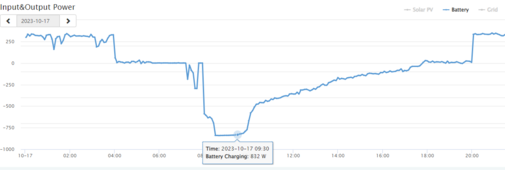
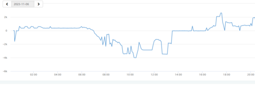
1. With 280Ah battery and nominal voltage of 51.2, theoretically, it can keep around 14kwh so 10-12kwh charge can help the battery to provide 70-80% DOD. Normally with this battery we apply charging current of 50-100A in 3-4 hours (depending on the solar power). When SOC is about 80, current will reduce gradually to even 20A or lower to keep cell voltage not exceeding 3.45, from 3.42-3.45 JK start to report SOC of 100%, however we can still charge to 3.45 at low current. As I observed on my Luxpower, it reduce charging current automatically so cell can go up to 3.45 without problem (see the charging power curve by LuxPower for my parrent house case with 50Ah battery). Lux can manage this charging curve quite smoothly using voltage when battery is served as lead acid. During this charging OVP (by BMS was not happened).
1711259760784.png2. ---Not applicable--
3. The discharging is applied according to night power demand. For my home, I expected the 7-8Kwh to be used over the night (5PM-5AM) so I set the max discharge current be 10A). See image with 100Ah battery on my other house
1711260123604.png
and here is the case for 280Ah battery in lead acid mode
1711260339444.png
In the nutshell, In Vietnam, we do apply charging from 7AM to 5PM and discharge with high current 10-25A from 5PM to 8PM then 10A for the remaining time. This approach is to keep best use of battery within the 3.2-3.45V while optimize energy for the night.
That was why I would recommend to simplify the charging approach to be CCCV and keep the absorption, floating period as longer as better to avoid OVP alarm by JKBMS. in my case I apply a checkpoint (as I said).
So I would recommend a wider option for user to choose such as:
1. Additional battery in parrallel;
2. Control on UVP, OVP;
3. Automatic control of charge/ discharge current based on the set limit for Charging, discharging current to ripple more energy without alarm from JK (if this happened, Inverter will show Notice that annoy people).
4. Introduce time range for discharge current would be best!
Best regard,
Ngoc
 
agree - very strange. Have you checked if one terminal of the cell is getting warmer/hotter than the others?
Also checked torque?
No. No.

It was torqued properly with a Wrench and digital Torque scale/indicator, so torque value should be fine. That was done approx 6 months ago.

And I doubt I'd see anything at 10a-20a near the top of the curve. There just aren't *that* many losses at such low current.

Torque wise, one thing that made me unhappy was that the studs were quite short, so I could only use the busbar + the provided flange nuts, not the proper flat washer + conical washer + nut as I would normally otherwise.

EDIT 1:
Not sure how much that translates into capacity difference between cells. Maybe it's only 1Ah maybe 5Ah (0.3%-2%) ...

But battery 01 definitively behaves much more consistently.

Battery 02 was unbalanced from the very start (cell 01 or 16 was on much lower voltage at the beginning, since it came from an older batch, since the original was leaking electrolyte and had to throw it away), but properly slowly ramped up the voltage 0.1V on the whole pack little by little over 36 hours. Then all cells were at 3.6V (back when I had the OVP set to 3.60V / 3.65V).

That was described in my other thread here: https://diysolarforum.com/threads/j...d-also-current-power-measurement.79913/page-3 (you can see a bit the voltage evolution, current was very small, but not in those pictures I believe)

You can see how battery 01 has all cells rising together, while battery 02 had some strange push-pull-pull back-push going on, even though it ultimately converges.
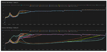
1711263177157.png


At first I thought it was BMS leads wrongly connected, but that would result in instability, not (although slowly) convergence. What was even more surprising was that one cell (turquoise ?) is the first to rise, then goes down a lot, then it's the last to come back ...

This was me raising the voltage 0.1V by 0.1V approx at a rate of 0.1V/hour pr 0.1V/2 hours using a programmable charger (Emerson / Vertiv R48).

But I believe part of the problem is that while the balancer discharges the highest cell, the charger recharges it, that's why it takes SO MUCH LONGER than if the charger (or inverter voltage) would just "back off a little". In that case, as stated in this thread here, I got from 3.55VDC to 3.42VDC in like 180 seconds only (charging disabled from BMS). Lowering the Charger voltage below pack voltage would effectively do the same thing (if PV is sufficient, battery will NOT be discharged).

EDIT 2:
@MrPablo: this is also related to what I was telling you before. It's NOT actually only the tolerances (on BMS and on Inverter) about the voltage measurement, it's also the fact that the voltage needs to be lower in order to give some headroom for the balancer to work without getting counter-acted by the Charger/Inverter.

Because say you are at 54.4 VDC on the Battery Pack (reported by BMS and measured with a multimeter) and 54.4 VDC on the Inverter/Charger (reported by Inverter/Charger and measured with a multimeter). As soon as the JK BMS will start discharging the highest voltage cell, the Inverter/Charger will recharge the pack, based on (54.4 VDC - delta_v_absorbed_by_balancer - 54.4 VDC) / ESR = - delta_v_absorbed_by_balancer / 0.005 Ohm or so ...

So while the JK BMS discharges the highest cell and before it recharges the lowest, you need to ensure that the Charger/Inverter voltage is AT LEAST delta_v_absorbed_by_balancer below the pack voltage. For every cycle of balance effectively ... You can probably calculate this dynamically based on the JK BMS supercapacitor capacitance value and battery capacity and voltage status. Otherwise you kinda get a capacitor multiplier / charge pump going on there (or a "very small" boost converter effectively, discharge highest cell, Inverter/Charge recharges it, JK recharges lowest cell).

EDIT 3:
And I am not so sure that the "Current Charge Control" of 0A works effectively. Again, tolerance measurements here as well on the Inverter Side (0A is very small compared to 240A nominal, so measurement offset / error can be significant with respect to "real" 0A). I set my parameters to Current Curve Factor 1 - End of Curve = 4.00 and Current Curve Factor 1 - Curve Shape = 1.80. It needs to be quite aggressive, in my case at least.

EDIT 4: On Battery 02, it could also be a case of "Balancer Induced Unbalance". Battery 02 was reporting approx. 0.7V HIGHER on pack/battery level (NOT a diode :ROFLMAO: ) than Battery 01 or the Multimeter (again on pack/battery level, i.e. 16 cells !). Battery 01 was also off by 0.1V (again on pack/battery level, i.e. 16 cells !), but nowhere Battery 02.

So you could say that it effectively started balancing at 3.45V - (0.7V/16 cells) = 3.406 V / cell. Well below the charge knee curve. So it probably created quite a bit of unbalance. I have since then calibrated the voltage reading (at NO LOAD !) and also lowered the OVP and OVPR values, since now the safety margin became smaller. But IIRC I have not "top balanced" the system after the voltage offset calibration (you can see in the attached picture there is still approx 0.05V / cell difference between Battery 01 and Battery 02).

EDIT 5: @MrPablo Maybe I can just set this to a NEGATIVE value, so that when Charge voltage is getting reduced by the ESP32, then the inverter will in effect stay a bit LOWER than the battery pack

# Inverter offset, allows you to correct the inverter charging voltage
inverter_offset_v: "-0.1"
 
Last edited:
By the way, esphome doesn't support OTA with the esp-idf framework. What are you using in order to get OTA running ? And what are the implications / side effects ?

 
Last edited:
By the way, esphome doesn't support OTA with the esp-idf framework. What are you using in order to get OTA running ? And what are the implications / side effects ?

There is a developing component named ota_http by @Olivier. I tested and worked but with a lot of effort! Wireguard can be ok with a bit of learning curve but I proposed Olivier to move on an automated firmware over mqtt and hopefully he will do!
 
There is a developing component named ota_http by @Olivier. I tested and worked but with a lot of effort! Wireguard can be ok with a bit of learning curve but I proposed Olivier to move on an automated firmware over mqtt and hopefully he will do!
Right now I just enabled the OTA component. I will anyway need to modify /etc/hosts (GNU/Linux) since the DNS isn't really working at the moment.

I don't like too much that the OTA password is transmitted plaintext and no encryption/SSL/TLS takes places. Regardless if it's the ota: section, the ota_http: section or the webserver: section.

Granted I need to firewall down my garage (right now it's just doing ip_forwarding to my main LAN so I can access stuff). But security wise it's an absolute no-go.

EDIT 1: when trying to enable the webserver (mainly for debugging purposes), I am getting some errors:
Code:
...
Compiling .pioenvs/jk-bms-bat02/src/esphome/components/wifi/wifi_component_esp_idf.o
Compiling .pioenvs/jk-bms-bat02/src/esphome/components/wifi/wifi_component_libretiny.o
Compiling .pioenvs/jk-bms-bat02/src/esphome/components/wifi/wifi_component_pico_w.o
Compiling .pioenvs/jk-bms-bat02/src/esphome/core/application.o
Compiling .pioenvs/jk-bms-bat02/src/esphome/core/component.o
Compiling .pioenvs/jk-bms-bat02/src/esphome/core/component_iterator.o
Compiling .pioenvs/jk-bms-bat02/src/esphome/core/controller.o
Compiling .pioenvs/jk-bms-bat02/src/esphome/core/entity_base.o
Compiling .pioenvs/jk-bms-bat02/src/esphome/core/helpers.o
Compiling .pioenvs/jk-bms-bat02/src/esphome/core/log.o
Compiling .pioenvs/jk-bms-bat02/src/esphome/core/ring_buffer.o
Compiling .pioenvs/jk-bms-bat02/src/esphome/core/scheduler.o
Compiling .pioenvs/jk-bms-bat02/src/esphome/core/string_ref.o
Compiling .pioenvs/jk-bms-bat02/src/esphome/core/util.o
Compiling .pioenvs/jk-bms-bat02/src/main.o
Linking .pioenvs/jk-bms-bat02/firmware.elf
/root/.platformio/packages/toolchain-xtensa-esp32s3/bin/../lib/gcc/xtensa-esp32s3-elf/8.4.0/../../../../xtensa-esp32s3-elf/bin/ld: .pioenvs/jk-bms-bat02/src/main.o:(.literal._Z5setupv+0xd38): undefined reference to `esphome::web_server::WebServer::WebServer(esphome::web_server_base::WebServerBase*)'
/root/.platformio/packages/toolchain-xtensa-esp32s3/bin/../lib/gcc/xtensa-esp32s3-elf/8.4.0/../../../../xtensa-esp32s3-elf/bin/ld: .pioenvs/jk-bms-bat02/src/main.o: in function `setup()':
/root/ESPHome/esphome-jk-bms-can-1.17.4/.esphome/build/jk-bms-bat02/src/main.cpp:579: undefined reference to `esphome::web_server::WebServer::WebServer(esphome::web_server_base::WebServerBase*)'
collect2: error: ld returned 1 exit status
*** [.pioenvs/jk-bms-bat02/firmware.elf] Error 1
========================================================================================= [FAILED] Took 41.70 seconds =========================================================================================

YAML relevant section:
YAML:
web_server:
  port: 80
  version: 2 # Version 1 displays as a table. Version 2 uses web components and has more functionality. Defaults to 2.
  log: true
  local: true # No internet/intranet required on the clients (all assets are inlined, compressed and served from flash)
  include_internal: true # Whether internal entities should be displayed on the web interface. Defaults to false
  ota: false
  auth:
    username: !secret web_server_username
    password: !secret web_server_password
 
By the way, esphome doesn't support OTA with the esp-idf framework. What are you using in order to get OTA running ? And what are the implications / side effects ?

where did you got the info that esp-idf does not support ota?
Im using both on all of my devices and it works out of the box without any problems and without any fancy or creepy stuff needed to be done.
 
Weird ... Now it seems to be working, both with WebServer v1 and v2.

Code:
Compiling .pioenvs/jk-bms-bat02/src/esphome/core/helpers.o
Compiling .pioenvs/jk-bms-bat02/src/esphome/core/log.o
Compiling .pioenvs/jk-bms-bat02/src/esphome/core/ring_buffer.o
Compiling .pioenvs/jk-bms-bat02/src/esphome/core/scheduler.o
Compiling .pioenvs/jk-bms-bat02/src/esphome/core/string_ref.o
Compiling .pioenvs/jk-bms-bat02/src/esphome/core/util.o
Compiling .pioenvs/jk-bms-bat02/src/main.o
Linking .pioenvs/jk-bms-bat02/firmware.elf
RAM:   [==        ]  15.7% (used 51552 bytes from 327680 bytes)
Flash: [========  ]  77.4% (used 1420913 bytes from 1835008 bytes)
Building .pioenvs/jk-bms-bat02/firmware.bin
Creating esp32s3 image...
Successfully created esp32s3 image.
esp32_create_combined_bin([".pioenvs/jk-bms-bat02/firmware.bin"], [".pioenvs/jk-bms-bat02/firmware.elf"])
Wrote 0x16afe0 bytes to file /root/ESPHome/esphome-jk-bms-can-1.17.4/.esphome/build/jk-bms-bat02/.pioenvs/jk-bms-bat02/firmware-factory.bin, ready to flash to offset 0x0
========================================================================================= [SUCCESS] Took 39.09 seconds =========================================================================================
INFO Successfully compiled program.
Found multiple options for uploading, please choose one:
  [1] /dev/ttyACM0 (USB JTAG/serial debug unit)
  [2] Over The Air (jk-bms-bat02.solar.stefano.home)

The "fix" was to set:
YAML:
esp32:
  board: {{board}}
  variant: {{variant}}
  framework:
    type: esp-idf
    version: latest

Let it fail with esp-idf framework 3.50102.240122, then roll back to
YAML:
esp32:
  board: {{board}}
  variant: {{variant}}
  framework:
    type: esp-idf

Build again.

Then it succeeds for some weird reason.
Perhaps you needed to build clean files, but worked around it with that approach?
 
where did you got the info that esp-idf does not support ota?
Im using both on all of my devices and it works out of the box without any problems and without any fancy or creepy stuff needed to be done.
In that page I linked, on the "web_server" component (https://esphome.io/components/web_server.html)
1711273494882.png

The web_server: ... ota: section apparently is NOT supported by the esp-idf framework.

The ota: section should be supported
YAML:
ota:
  safe_mode: true
  password: !secret ota_password
  on_begin:
    then:
      - lambda: id(enable_bluetooth_connection).turn_off();
      - logger.log: "BLE shutdown for flashing"


EDIT 1:
While this OTA part is NOT supported according to the docs:
YAML:
web_server:
  port: 80
  version: 2 # Version 1 displays as a table. Version 2 uses web components and has more functionality. Defaults to 2.
  log: true
  local: true # NOT SUPPORTED IN VERSION 1 - No internet/intranet required on the clients (all assets are inlined, compressed and served from flash)
  include_internal: true # Whether internal entities should be displayed on the web interface. Defaults to false
  #css_include: "v1/www.css"  # v1
  #css_url: ""                # v1
  #js_include: "v1/www.js"    # v1
  #js_url: ""                 # v1
  #css_include: ""             # v2
  css_url: ""                 # v2
  js_include: "v2/www.js"     # v2
  js_url: ""                  # v2
  ota: false                  # <------------------ This is NOT supported by the esp-idf framework according to ESPHome Documentation
  auth:
    username: !secret web_server_username
    password: !secret web_server_password
 
Right now I just enabled the OTA component. I will anyway need to modify /etc/hosts (GNU/Linux) since the DNS isn't really working at the moment.

I don't like too much that the OTA password is transmitted plaintext and no encryption/SSL/TLS takes places. Regardless if it's the ota: section, the ota_http: section or the webserver: section.

Granted I need to firewall down my garage (right now it's just doing ip_forwarding to my main LAN so I can access stuff). But security wise it's an absolute no-go.

EDIT 1: when trying to enable the webserver (mainly for debugging purposes), I am getting some errors:
Code:
...
Compiling .pioenvs/jk-bms-bat02/src/esphome/components/wifi/wifi_component_esp_idf.o
Compiling .pioenvs/jk-bms-bat02/src/esphome/components/wifi/wifi_component_libretiny.o
Compiling .pioenvs/jk-bms-bat02/src/esphome/components/wifi/wifi_component_pico_w.o
Compiling .pioenvs/jk-bms-bat02/src/esphome/core/application.o
Compiling .pioenvs/jk-bms-bat02/src/esphome/core/component.o
Compiling .pioenvs/jk-bms-bat02/src/esphome/core/component_iterator.o
Compiling .pioenvs/jk-bms-bat02/src/esphome/core/controller.o
Compiling .pioenvs/jk-bms-bat02/src/esphome/core/entity_base.o
Compiling .pioenvs/jk-bms-bat02/src/esphome/core/helpers.o
Compiling .pioenvs/jk-bms-bat02/src/esphome/core/log.o
Compiling .pioenvs/jk-bms-bat02/src/esphome/core/ring_buffer.o
Compiling .pioenvs/jk-bms-bat02/src/esphome/core/scheduler.o
Compiling .pioenvs/jk-bms-bat02/src/esphome/core/string_ref.o
Compiling .pioenvs/jk-bms-bat02/src/esphome/core/util.o
Compiling .pioenvs/jk-bms-bat02/src/main.o
Linking .pioenvs/jk-bms-bat02/firmware.elf
/root/.platformio/packages/toolchain-xtensa-esp32s3/bin/../lib/gcc/xtensa-esp32s3-elf/8.4.0/../../../../xtensa-esp32s3-elf/bin/ld: .pioenvs/jk-bms-bat02/src/main.o:(.literal._Z5setupv+0xd38): undefined reference to `esphome::web_server::WebServer::WebServer(esphome::web_server_base::WebServerBase*)'
/root/.platformio/packages/toolchain-xtensa-esp32s3/bin/../lib/gcc/xtensa-esp32s3-elf/8.4.0/../../../../xtensa-esp32s3-elf/bin/ld: .pioenvs/jk-bms-bat02/src/main.o: in function `setup()':
/root/ESPHome/esphome-jk-bms-can-1.17.4/.esphome/build/jk-bms-bat02/src/main.cpp:579: undefined reference to `esphome::web_server::WebServer::WebServer(esphome::web_server_base::WebServerBase*)'
collect2: error: ld returned 1 exit status
*** [.pioenvs/jk-bms-bat02/firmware.elf] Error 1
========================================================================================= [FAILED] Took 41.70 seconds =========================================================================================

YAML relevant section:
YAML:
web_server:
  port: 80
  version: 2 # Version 1 displays as a table. Version 2 uses web components and has more functionality. Defaults to 2.
  log: true
  local: true # No internet/intranet required on the clients (all assets are inlined, compressed and served from flash)
  include_internal: true # Whether internal entities should be displayed on the web interface. Defaults to false
  ota: false
  auth:
    username: !secret web_server_username
    password: !secret web_server_password
I´m using web_server too for debugging, but without log, OTA

This is the OTA component i´m talking about:

this is also in included on the GH repo and should work fine - if that does not work for your LAN setup, maybe consider using a fixed IP for the ESP would help - does your esps shows as online in the ESPhome dashboard?

regarding your compile error: Just clean the buildfiles and it will compile :)
 

diy solar

diy solar
Back
Top