diy solar

diy solar

YamBMS JK-BMS-CAN with new Cut-Off Charging Logic (open-source)

Right now I just enabled the OTA component. I will anyway need to modify /etc/hosts (GNU/Linux) since the DNS isn't really working at the moment.

I don't like too much that the OTA password is transmitted plaintext and no encryption/SSL/TLS takes places. Regardless if it's the ota: section, the ota_http: section or the webserver: section.

Granted I need to firewall down my garage (right now it's just doing ip_forwarding to my main LAN so I can access stuff). But security wise it's an absolute no-go.

EDIT 1: when trying to enable the webserver (mainly for debugging purposes), I am getting some errors:
Code:
...
Compiling .pioenvs/jk-bms-bat02/src/esphome/components/wifi/wifi_component_esp_idf.o
Compiling .pioenvs/jk-bms-bat02/src/esphome/components/wifi/wifi_component_libretiny.o
Compiling .pioenvs/jk-bms-bat02/src/esphome/components/wifi/wifi_component_pico_w.o
Compiling .pioenvs/jk-bms-bat02/src/esphome/core/application.o
Compiling .pioenvs/jk-bms-bat02/src/esphome/core/component.o
Compiling .pioenvs/jk-bms-bat02/src/esphome/core/component_iterator.o
Compiling .pioenvs/jk-bms-bat02/src/esphome/core/controller.o
Compiling .pioenvs/jk-bms-bat02/src/esphome/core/entity_base.o
Compiling .pioenvs/jk-bms-bat02/src/esphome/core/helpers.o
Compiling .pioenvs/jk-bms-bat02/src/esphome/core/log.o
Compiling .pioenvs/jk-bms-bat02/src/esphome/core/ring_buffer.o
Compiling .pioenvs/jk-bms-bat02/src/esphome/core/scheduler.o
Compiling .pioenvs/jk-bms-bat02/src/esphome/core/string_ref.o
Compiling .pioenvs/jk-bms-bat02/src/esphome/core/util.o
Compiling .pioenvs/jk-bms-bat02/src/main.o
Linking .pioenvs/jk-bms-bat02/firmware.elf
/root/.platformio/packages/toolchain-xtensa-esp32s3/bin/../lib/gcc/xtensa-esp32s3-elf/8.4.0/../../../../xtensa-esp32s3-elf/bin/ld: .pioenvs/jk-bms-bat02/src/main.o:(.literal._Z5setupv+0xd38): undefined reference to `esphome::web_server::WebServer::WebServer(esphome::web_server_base::WebServerBase*)'
/root/.platformio/packages/toolchain-xtensa-esp32s3/bin/../lib/gcc/xtensa-esp32s3-elf/8.4.0/../../../../xtensa-esp32s3-elf/bin/ld: .pioenvs/jk-bms-bat02/src/main.o: in function `setup()':
/root/ESPHome/esphome-jk-bms-can-1.17.4/.esphome/build/jk-bms-bat02/src/main.cpp:579: undefined reference to `esphome::web_server::WebServer::WebServer(esphome::web_server_base::WebServerBase*)'
collect2: error: ld returned 1 exit status
*** [.pioenvs/jk-bms-bat02/firmware.elf] Error 1
========================================================================================= [FAILED] Took 41.70 seconds =========================================================================================

YAML relevant section:
YAML:
web_server:
  port: 80
  version: 2 # Version 1 displays as a table. Version 2 uses web components and has more functionality. Defaults to 2.
  log: true
  local: true # No internet/intranet required on the clients (all assets are inlined, compressed and served from flash)
  include_internal: true # Whether internal entities should be displayed on the web interface. Defaults to false
  ota: false
  auth:
    username: !secret web_server_username
    password: !secret web_server_password
It might be not relating to yours writing but for my case with 3 devices in 3 different places, hundred of km away from each other, I have 2 options:
1. Using OTA with 2 options:
+ Using NAT (i.e 8266:public to 8266: internal) at the router of each site on 8266 or whatever port specified for the internal Esphome: This work for months already but requires a bit of configuring; Esphome device connect to HA via mqtt;
With this option I will have to use the use_address in the Wifi section. (use_address: [no ip dyn]);
+ using ota_http: a bit of problem to generate firmware (in legacy format), md5 hash and post to a webserver. I myself post it to my HA with additional web server installed via root ssh.
2. Using wireguard: installing wireguard is abit difficult but also worked!
Currently, I propose Olivier and his team to modify his ota_http to allow firmware update over the mqtt protocol (this can be best as it is easy and can be fully automated via the esphome's Install command) but they seems to be reluctantly to do so!

Regarding the improvement of charging, I am working on modifying Sleeper85 code (the old version) on 0x355 and 0x351 to simply focus on:
+ Create a script to handle the charging/discharging check using cell voltage (min/max) and check point set by user (such as 3.2 - 3.45) to start reducing charging current when max cell voltage is closing to 3.45 or OVP slider value set by user. Similarly will be applied for UVP. I prefer to use map() or PID to fine tune charging current.
+ On SOC reporting: stick to 99% (regardless JK SOC is 100 already) until 3.45 or max check point on OVP is reached. The same logic shall be applied while discharging: if voltage fall below 3.2 or checkpoint set by user while JK SOC is greater than the cutoff value for inverter, it will still set SOC to the cut off value to stop discharging. If SOC is fall below the Cutoff value but Cell minimum voltage is still greater than 3.2 or OVP value, it will report SOC of 1 point higher than the Cutoff value. By doing this, JK will reset its SOC to the nearly acceptable value.
Best
Ngoc

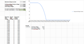
For your first modification about charging current, you can achieve the same result by setting
Current Curve Factor 1 - End of Curve = 4.00 or 5.00
Current Curve Factor 1 - Curve Shape = 1.80

1711274166275.png

For SOC reporting, it should be done similarly to what Victron Smartshunt behaves:
- Voltage > 55.2 V (or whatever bulk is set)
- Current < 0.5% or something like that (Tail current is very small)
- Time when both true: > 10 min or so

If these conditions are met, SOC shall be set to 100%.

About undervoltage and SOC reporting, be careful ... you don't want to report 0% all of a sudden just because you have a transient voltage drop due to a load step.
 
It was torqued properly with a Wrench and digital Torque scale/indicator, so torque value should be fine. That was done approx 6 months ago.

And I doubt I'd see anything at 10a-20a near the top of the curve. There just aren't *that* many losses at such low current.
if one terminal has a higher resistant, there will be burned more energy during the charging cycle at higher currents - and that energy is then missing on that cell - so i would suggest (just to be sure) checking the temps and torgue again. But maybe its just a bad cell there.

Torque wise, one thing that made me unhappy was that the studs were quite short, so I could only use the busbar + the provided flange nuts, not the proper flat washer + conical washer + nut as I would normally otherwise.
i hade the same problem on one pack i had to rework for a friend - i used some normal nuts which have only half of the hight from normal nuts to use washers and springwashers on top of the busbars - that worked out great so far :)

Overall your curves are really weird - wil have a look on your other thread the next days
 
if one terminal has a higher resistant, there will be burned more energy during the charging cycle at higher currents - and that energy is then missing on that cell - so i would suggest (just to be sure) checking the temps and torgue again. But maybe its just a bad cell there.


i hade the same problem on one pack i had to rework for a friend - i used some normal nuts which have only half of the hight from normal nuts to use washers and springwashers on top of the busbars - that worked out great so far :)

Overall your curves are really weird - wil have a look on your other thread the next days
I'm a bit skeptical but everything can be. I'm also human :ROFLMAO: .

- Terminals were properly cleaned with red scotchbrite
- Terminals were cleaned with isopropyl alcohol
- Applied generous amount of MG Chem 842 Graphite Conductive Paste
- Busbars were cleaned with isopropyl alcohol
- Torqued to the required torque setting (cannot remember now, these studs cannot take much, maybe was it 3.0Nm or 3.5Nm ???)

Agreed that the curves look very weird.

But what is the alternative ? That pack is in operation right now ... Worst, the two batteries are in the same enclosure so maintenance is an absolute nightmare.

Save a few EUR on the box, complicated everything else 🥴.

If it's a bad cell and it needs to be replaced, I think it's a whole battery transpant into the new battery v02 boxes (wooden boxes), with only one battery per box, and adding a NEEY active balancer + Victron Smartshunt on each battery.
 
It might be not relating to yours writing but for my case with 3 devices in 3 different places, hundred of km away from each other, I have 2 options:
1. Using OTA with 2 options:
+ Using NAT (i.e 8266:public to 8266: internal) at the router of each site on 8266 or whatever port specified for the internal Esphome: This work for months already but requires a bit of configuring; Esphome device connect to HA via mqtt;
With this option I will have to use the use_address in the Wifi section. (use_address: [no ip dyn]);
+ using ota_http: a bit of problem to generate firmware (in legacy format), md5 hash and post to a webserver. I myself post it to my HA with additional web server installed via root ssh.
2. Using wireguard: installing wireguard is abit difficult but also worked!
Currently, I propose Olivier and his team to modify his ota_http to allow firmware update over the mqtt protocol (this can be best as it is easy and can be fully automated via the esphome's Install command) but they seems to be reluctantly to do so!

Regarding the improvement of charging, I am working on modifying Sleeper85 code (the old version) on 0x355 and 0x351 to simply focus on:
+ Create a script to handle the charging/discharging check using cell voltage (min/max) and check point set by user (such as 3.2 - 3.45) to start reducing charging current when max cell voltage is closing to 3.45 or OVP slider value set by user. Similarly will be applied for UVP. I prefer to use map() or PID to fine tune charging current.
+ On SOC reporting: stick to 99% (regardless JK SOC is 100 already) until 3.45 or max check point on OVP is reached. The same logic shall be applied while discharging: if voltage fall below 3.2 or checkpoint set by user while JK SOC is greater than the cutoff value for inverter, it will still set SOC to the cut off value to stop discharging. If SOC is fall below the Cutoff value but Cell minimum voltage is still greater than 3.2 or OVP value, it will report SOC of 1 point higher than the Cutoff value. By doing this, JK will reset its SOC to the nearly acceptable value.
Best
Ngoc
About the OTA/NAT/Wireguard .... Couldn't you also simply have a OpenWRT / Turris / Custom router and do it from there ?

Like SSH/Wireguard into the router, then do the OTA from there to the ESP32 ?

Or you don't have access to that router and/or it's not an "open" one (cannot do advanced stuff) ?
 
I´m using web_server too for debugging, but without log, OTA

This is the OTA component i´m talking about:

this is also in included on the GH repo and should work fine - if that does not work for your LAN setup, maybe consider using a fixed IP for the ESP would help - does your esps shows as online in the ESPhome dashboard?

regarding your compile error: Just clean the buildfiles and it will compile :)
I updated my script to ask the user, at the end, in case of errors, if he wants to clean + try again.
Thanks for the suggestion.
Here is the updated file:

(lines 75-81)

Bash:
# Manage errors & try again
echo -e "In case of errors, it is suggested to run: esphome clean.\n"
read -p "Do you want to clean the build files & try build again: [Y/N] " tryagain
echo -e "\n"

# Clean build files and try again ?
if [ "$tryagain" == "Y" ] || [ "$tryagain" == "y" ]
then
   # Run clean & try again"
   esphome clean $esphomeconfig
   esphome run $esphomeconfig
fi
 
By the way, where (if anything) do you put the included CAN Termination Resistor that is delivered together with the M5Stack CANBus Unit (CA-IS3050G) / SKU: U085 ?
 
By the way, where (if anything) do you put the included CAN Termination Resistor that is delivered together with the M5Stack CANBus Unit (CA-IS3050G) / SKU: U085 ?
As it's a bus with the inverter at one end, ESP32 at the other (for now at least), put the 120ohm resistor across the high and low on the ESP32.

That will properly terminate the bus, reducing errors.
 
About the OTA/NAT/Wireguard .... Couldn't you also simply have a OpenWRT / Turris / Custom router and do it from there ?

Like SSH/Wireguard into the router, then do the OTA from there to the ESP32 ?

Or you don't have access to that router and/or it's not an "open" one (cannot do advanced stuff) ?
They are all ISP routers and they only support NAT. Anyway, this trick is still worked for now! no worry Silverstone. I only run 6 of inverter in places and they are connected to my HA at my home. What I am trying to achieve is getting the high capacity battery be charge properly and I found Sleeper85 yaml (the old version) is mostly acceptable to the moment with little modification comparing to Uksa007 or someone else. And I decided to stop here to focus on the approach that Sleeper85, Mr.Pablo and other is talking on this topic to help it better fitting our needs!
 
As it's a bus with the inverter at one end, ESP32 at the other (for now at least), put the 120ohm resistor across the high and low on the ESP32.

That will properly terminate the bus, reducing errors.
Alright, thanks. I was wondering the ESP32 had its own integrated already and the resistor was for the Deye :ROFLMAO: .
 
As it's a bus with the inverter at one end, ESP32 at the other (for now at least), put the 120ohm resistor across the high and low on the ESP32.

That will properly terminate the bus, reducing errors.
In my case i use esp32-s2 lolin and a tja1050 and it worked smoothly with deye and luxpower without even the 120 Ohm resister. I made prototype and have them work stably in 5 locations for 2 months by now!
1711276930415.png1711276964270.png
 
They are all ISP routers and they only support NAT. Anyway, this trick is still worked for now! no worry Silverstone. I only run 6 of inverter in places and they are connected to my HA at my home. What I am trying to achieve is getting the high capacity battery be charge properly and I found Sleeper85 yaml (the old version) is mostly acceptable to the moment with little modification comparing to Uksa007 or someone else. And I decided to stop here to focus on the approach that Sleeper85, Mr.Pablo and other is talking on this topic to help it better fitting our needs!
My suggestion would be to work together, so if you do a fork, submit a pull request so that everybody can benefit (y).

And its also easier for you, instead of always backporting features etc.
 
My suggestion would be to work together, so if you do a fork, submit a pull request so that everybody can benefit (y).

And its also easier for you, instead of always backporting features etc.
Yeah, I will do for sure! because the fork version based on Sleeper85 version posted in Jan and now I come back and discovered a lot of changes. This make I feel a bit of worrying (however, 2 days ago, i build a test device for my 100Ah battery and would like to report the result)! And currently keep working on my own first to test before sharing back to Sleeper85 and Pablo for not annoying them and others! This also the reason for me to raise some points of experience from our community (those are mostly benefited from open forum like this and keep applying into our owned work!)
Many thanks for your advise then!
Best
 
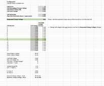
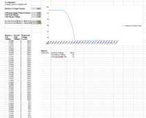
@MrPablo: not sure if it's a bug/feature of the Spreadsheet, but also trying the reverse case (all cells below 3.45V, one sitting even lower), the charge voltage gets REDUCED for the lower cell ...

1711277896167.png

So the charge voltage logic needs to be reviewed carefully in my opinion.

If possible, please let me know if this is an assumption of the spreadsheet or a real issue in the code (y) .
 
@MrPablo: not sure if it's a bug/feature of the Spreadsheet, but also trying the reverse case (all cells below 3.45V, one sitting even lower), the charge voltage gets REDUCED for the lower cell ...

View attachment 204156

So the charge voltage logic needs to be reviewed carefully in my opinion.

If possible, please let me know if this is an assumption of the spreadsheet or a real issue in the code (y) .
The logic of the code means it will proportionally disregard a cell that is lower than the majority of cells.
If you were to add the 'missing' 50mv to the requested CVL, that additional voltage is unlikely to boost the lagging cell. Instead, it's likely that it'll push a higher cell more, potentially exceeding target voltage.

The knee effect is why we can't just sum up the cell difference to target voltage, then add that on top of actual battery voltage.

I think we've already established that this logic is going to be rewritten, but this is expected behaviour in it's current state.

In an ideal world, we'd be running a balance charger where each cell is individually charged, making true per cell management possible.
 
Concerning Current Charge Control, I set it very aggressive to 6.0 even ... that way nothing should be pushed into the battery above 3.45 V

Let's see ... Right now I have battery at 65% but not much sun, mostly clouds, so it's actually getting DISCHARGED :ROFLMAO: .


1711279274556.png
 
The logic of the code means it will proportionally disregard a cell that is lower than the majority of cells.
If you were to add the 'missing' 50mv to the requested CVL, that additional voltage is unlikely to boost the lagging cell. Instead, it's likely that it'll push a higher cell more, potentially exceeding target voltage.

The knee effect is why we can't just sum up the cell difference to target voltage, then add that on top of actual battery voltage.

I think we've already established that this logic is going to be rewritten, but this is expected behaviour in it's current state.
No, you have a fair point (y). The higher cells will likely rise before the lower one can catch up, that's also what I could observe.
 
Damn .. When I am (almost) ready to do some testing, the sun is not shining and the battery is getting discharged :rolleyes:
 
Well I'll try to hook it up anyway. I think I'll leave the BMS_Err_Stop unchecked, as I don't really want my system to trip ...

1711280681882.png
 
@MrPablo : it doesn't appear to be working... Both BLE and Wi-Fi are not working at the moment. At least the Atom S3 Lite is not getting an IP from DHCP server. Only sign that it's on is the fact that the light on the CAN hat is illuminated

Considering this is very similar to syssi code it's definitively unexpected
 
it definitively doesn't say much in the logs. COMPLETELY DIFFERENT than ESP32 devices I am currently using with the syssi code.

With ESP32 it used to produce much more user friendly results. And In DEBUG mode it would list all WiFi networks available, status of the BLE connection, etc.

Not so with the Atom S3 Lite ...

Code:
INFO ESPHome 2024.3.0
INFO Reading configuration esp32-ble-1.17.4.yaml...
INFO Updating https://github.com/syssi/esphome-jk-bms.git@main
INFO Detected timezone 'Europe/Copenhagen'
INFO Generating C++ source...
INFO Compiling app...
Processing jk-bms-bat02 (board: esp32-s3-devkitc-1; framework: espidf; platform: platformio/espressif32@5.4.0)
---------------------------------------------------------------------------------------------------------------------------------------
HARDWARE: ESP32S3 240MHz, 320KB RAM, 8MB Flash
 - framework-espidf @ 3.40406.240122 (4.4.6)
 - tool-cmake @ 3.16.4
 - tool-ninja @ 1.7.1
 - toolchain-esp32ulp @ 2.35.0-20220830
 - toolchain-riscv32-esp @ 8.4.0+2021r2-patch5
 - toolchain-xtensa-esp32s3 @ 8.4.0+2021r2-patch5
Reading CMake configuration...
Dependency Graph
|-- ArduinoJson @ 6.18.5
Compiling .pioenvs/jk-bms-bat02/src/main.o
Linking .pioenvs/jk-bms-bat02/firmware.elf
RAM:   [==        ]  16.3% (used 53552 bytes from 327680 bytes)
Flash: [========  ]  81.5% (used 1495461 bytes from 1835008 bytes)
Building .pioenvs/jk-bms-bat02/firmware.bin
Creating esp32s3 image...
Successfully created esp32s3 image.
esp32_create_combined_bin([".pioenvs/jk-bms-bat02/firmware.bin"], [".pioenvs/jk-bms-bat02/firmware.elf"])
Wrote 0x17d310 bytes to file /root/ESPHome/esphome-jk-bms-can-1.17.4/.esphome/build/jk-bms-bat02/.pioenvs/jk-bms-bat02/firmware-factory.bin, ready to flash to offset 0x0
==================================================== [SUCCESS] Took 70.01 seconds ====================================================
INFO Successfully compiled program.
Found multiple options for uploading, please choose one:
  [1] /dev/ttyACM0 (USB JTAG/serial debug unit)
  [2] Over The Air (jk-bms-bat02.solar.stefano.home)
(number): 1
esptool.py v4.7.0
Serial port /dev/ttyACM0
Connecting...
Chip is ESP32-S3 (QFN56) (revision v0.2)
Features: WiFi, BLE, Embedded Flash 8MB (GD)
Crystal is 40MHz
MAC: 34:b7:da:54:d7:08
Uploading stub...
Running stub...
Stub running...
Changing baud rate to 460800
Changed.
Configuring flash size...
Auto-detected Flash size: 8MB
Flash will be erased from 0x00010000 to 0x0017dfff...
Flash will be erased from 0x00000000 to 0x00005fff...
Flash will be erased from 0x00008000 to 0x00008fff...
Flash will be erased from 0x00009000 to 0x0000afff...
Compressed 1495824 bytes to 940387...
Wrote 1495824 bytes (940387 compressed) at 0x00010000 in 9.8 seconds (effective 1224.1 kbit/s)...
Hash of data verified.
Warning: Image file at 0x0 is protected with a hash checksum, so not changing the flash size setting. Use the --flash_size=keep option instead of --flash_size=8MB in order to remove this warning, or use the --dont-append-digest option for the elf2image command in order to generate an image file without a hash checksum
Compressed 20912 bytes to 13093...
Wrote 20912 bytes (13093 compressed) at 0x00000000 in 0.3 seconds (effective 492.0 kbit/s)...
Hash of data verified.
Compressed 3072 bytes to 134...
Wrote 3072 bytes (134 compressed) at 0x00008000 in 0.0 seconds (effective 556.9 kbit/s)...
Hash of data verified.
Compressed 8192 bytes to 31...
Wrote 8192 bytes (31 compressed) at 0x00009000 in 0.1 seconds (effective 899.2 kbit/s)...
Hash of data verified.

Leaving...
Hard resetting via RTS pin...
INFO Successfully uploaded program.
INFO Starting log output from /dev/ttyACM0 with baud rate 115200
[13:59:48]ESP-ROM:esp32s3-20210327
[13:59:48]Build:Mar 27 2021
[13:59:48]rst:0x7 (TG0WDT_SYS_RST),boot:0x28 (SPI_FAST_FLASH_BOOT)
[13:59:48]Saved PC:0x400454d5
[13:59:48]SPIWP:0xee
[13:59:48]mode:QIO, clock div:1
[13:59:48]load:0x3fce3808,len:0x1658
[13:59:48]ets_loader.c 78
[13:59:49]ESP-ROM:esp32s3-20210327
[13:59:49]Build:Mar 27 2021
[13:59:49]rst:0x7 (TG0WDT_SYS_RST),boot:0x28 (SPI_FAST_FLASH_BOOT)
[13:59:49]Saved PC:0x400454d5
[13:59:49]SPIWP:0xee
[13:59:49]mode:QIO, clock div:1
[13:59:49]load:0x3fce3808,len:0x1658
[13:59:49]ets_loader.c 78
[13:59:50]ESP-ROM:esp32s3-20210327
[13:59:50]Build:Mar 27 2021
[13:59:50]rst:0x7 (TG0WDT_SYS_RST),boot:0x28 (SPI_FAST_FLASH_BOOT)
[13:59:50]Saved PC:0x400454d5
[13:59:50]SPIWP:0xee
[13:59:50]mode:QIO, clock div:1
[13:59:50]load:0x3fce3808,len:0x1658
[13:59:50]ets_loader.c 78
[13:59:52]ESP-ROM:esp32s3-20210327
[13:59:52]Build:Mar 27 2021
[13:59:52]rst:0x7 (TG0WDT_SYS_RST),boot:0x28 (SPI_FAST_FLASH_BOOT)
[13:59:52]Saved PC:0x400454d5
[13:59:52]SPIWP:0xee
[13:59:52]mode:QIO, clock div:1
[13:59:52]load:0x3fce3808,len:0x1658
[13:59:52]ets_loader.c 78
[13:59:53]ESP-ROM:esp32s3-20210327
[13:59:53]Build:Mar 27 2021
[13:59:53]rst:0x7 (TG0WDT_SYS_RST),boot:0x28 (SPI_FAST_FLASH_BOOT)
[13:59:53]Saved PC:0x400454d5
[13:59:53]SPIWP:0xee
[13:59:53]mode:QIO, clock div:1
[13:59:53]load:0x3fce3808,len:0x1658
[13:59:53]ets_loader.c 78
[13:59:54]ESP-ROM:esp32s3-20210327
[13:59:54]Build:Mar 27 2021
[13:59:54]rst:0x7 (TG0WDT_SYS_RST),boot:0x28 (SPI_FAST_FLASH_BOOT)
[13:59:54]Saved PC:0x400454d5
[13:59:54]SPIWP:0xee
[13:59:54]mode:QIO, clock div:1
[13:59:54]load:0x3fce3808,len:0x1658
[13:59:54]ets_loader.c 78
[13:59:56]ESP-ROM:esp32s3-20210327
[13:59:56]Build:Mar 27 2021
[13:59:56]rst:0x7 (TG0WDT_SYS_RST),boot:0x28 (SPI_FAST_FLASH_BOOT)
[13:59:56]Saved PC:0x400454d5
[13:59:56]SPIWP:0xee
[13:59:56]mode:QIO, clock div:1
[13:59:56]load:0x3fce3808,len:0x1658
[13:59:56]ets_loader.c 78
[13:59:57]ESP-ROM:esp32s3-20210327
[13:59:57]Build:Mar 27 2021
[13:59:57]rst:0x7 (TG0WDT_SYS_RST),boot:0x28 (SPI_FAST_FLASH_BOOT)
[13:59:57]Saved PC:0x400454d5
[13:59:57]SPIWP:0xee
[13:59:57]mode:QIO, clock div:1
[13:59:57]load:0x3fce3808,len:0x1658
[13:59:57]ets_loader.c 78
[13:59:58]ESP-ROM:esp32s3-20210327
[13:59:58]Build:Mar 27 2021
[13:59:58]rst:0x7 (TG0WDT_SYS_RST),boot:0x28 (SPI_FAST_FLASH_BOOT)
[13:59:58]Saved PC:0x400454d5
[13:59:58]SPIWP:0xee
[13:59:58]mode:QIO, clock div:1
[13:59:58]load:0x3fce3808,len:0x1658
[13:59:58]ets_loader.c 78

EDIT: By the way, I am also getting this warning during compile. Are you also getting this ?
Code:
Compiling .pioenvs/jk-bms-bat02/src/esphome/components/jk_bms_ble/button/jk_button.o
src/esphome/components/esp32_can/esp32_can.cpp: In member function 'virtual esphome::canbus::Error esphome::esp32_can::ESP32Can::send_message(esphome::canbus::CanFrame*)':
src/esphome/components/esp32_can/esp32_can.cpp:114:3: warning: missing initializer for member 'twai_message_t::data' [-Wmissing-field-initializers]
   };
   ^
 
I don't personally run the S3 lite, but I know there's some ongoing discussion on GitHub at the below link:

As for the warning during compile, I've seen that since last year without issue.
 
I don't personally run the S3 lite, but I know there's some ongoing discussion on GitHub at the below link:

As for the warning during compile, I've seen that since last year without issue.
Alright thanks ... it seems each ESP32 variant had its quirks.

I added the following to the YAML file
YAML:
board_build.flash_mode: dio

I also included this in the YAML file, which was in one of the issues report from syssi code (for ESP32 in this case, not specifically S3):
YAML:
    build_flags:
      - -DCONFIG_ARDUINO_LOOP_STACK_SIZE=32768

EDIT: with BOTH these options, when attached to the PC, the boot process looks much similar to the ESP32 before with syssi code. Now I need to recompile with logger: level: INFO (logger: level: DEBUG causes periodic disconnects apparently). Not sure if BOTH options are really necessary. I also had added logger: hardware_uart: USB_SERIAL_JTAG, that I did NOT have with syssi code ...
 
Last edited:
Alright thanks ... it seems each ESP32 variant had its quirks.

I added the following to the YAML file
YAML:
board_build.flash_mode: dio

I also included this in the YAML file, which was in one of the issues report from syssi code (for ESP32 in this case, not specifically S3):
YAML:
    build_flags:
      - -DCONFIG_ARDUINO_LOOP_STACK_SIZE=32768

EDIT: with BOTH these options, when attached to the PC, the boot process looks much similar to the ESP32 before with syssi code. Now I need to recompile with logger: level: INFO (logger: level: DEBUG causes periodic disconnects apparently). Not sure if BOTH options are really necessary. I also had added logger: hardware_uart: USB_SERIAL_JTAG, that I did NOT have with syssi code ...

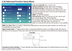
If you reference this file, you can see that USB_SERIAL_JTAG is required to make the S3 lite work correctly when using the wired connection to JK BMS.

The version under development will be more robust when dealing with the many hardware variations.
 

If you reference this file, you can see that USB_SERIAL_JTAG is required to make the S3 lite work correctly when using the wired connection to JK BMS.

The version under development will be more robust when dealing with the many hardware variations.
But I'm using BLE. So maybe it was required, maybe not.

Some weird stuff in Home Assistant though ...
1711287560883.png

I was expecting it to just replace syssi ESP32, but apparently it registered as a new device.

But the Battery is still associated with the old one ...

Do I need to change something on HA or on the MQTT broker to mark this change ?
 

diy solar

diy solar
Back
Top