


You are using an out of date browser. It may not display this or other websites correctly.
You should upgrade or use an alternative browser.
You should upgrade or use an alternative browser.
YamBMS JK-BMS-CAN with new Cut-Off Charging Logic (open-source)
- Thread starter Sleeper85
- Start date
silverstone
Solar Enthusiast
- Joined
- May 3, 2022
- Messages
- 1,050
Where should that be set ? Isn't it as per default ?Have you checked the baud rate is set correctly.
In the code in the section "Do NOT modify" it seems to be set at 500kbps
YAML:
# +--------------------------------------+
# | Start CAN Handling                   |
# +--------------------------------------+
canbus: # 0x305 - Inverter ACK - SMA/LG/Pylon/Goodwe reply
  - platform: esp32_can
    tx_pin: ${can_tx_pin}
    rx_pin: ${can_rx_pin}
    can_id: 4
    bit_rate: 500kbps
    on_frame:
    - can_id: 0x305
      then:
        - light.toggle:
            id: blue_led
        - lambda: |-
            id(can_ack_counter) = 0;                              // Reset ACK counter
            id(can_bus_status).publish_state(true);               // Set CANBUS Status to ON
ESP_LOGI("main", "received can id: 0x305 ACK");silverstone
Solar Enthusiast
- Joined
- May 3, 2022
- Messages
- 1,050
Something is completely off.
I tried AGAIN with reversing pin 4 and pin 5 on the RJ45.
Nothing happens ... AGAIN .
.
It seems that ESP32 sends CAN data, but nothing is received on the inverter side.
I tried AGAIN with reversing pin 4 and pin 5 on the RJ45.
Nothing happens ... AGAIN
.
Code:
Client null sending PINGREQ
Client null received PINGRESP
Client null received PUBLISH (d0, q0, r0, m0, 'jk-bms-bat02/debug', ... (79 bytes))
jk-bms-bat02/debug [I][jk_bms_ble:327]: Cell info frame (version 2, 300 bytes) received
Client null received PUBLISH (d0, q0, r0, m0, 'jk-bms-bat02/debug', ... (94 bytes))
jk-bms-bat02/debug [W][component:232]: Component esp32_ble took a long time for an operation (132 ms).
Client null received PUBLISH (d0, q0, r0, m0, 'jk-bms-bat02/debug', ... (73 bytes))
jk-bms-bat02/debug [W][component:233]: Components should block for at most 30 ms.
Client null received PUBLISH (d0, q0, r0, m0, 'jk-bms-bat02/debug', ... (79 bytes))
jk-bms-bat02/debug [I][jk_bms_ble:327]: Cell info frame (version 2, 300 bytes) received
Client null received PUBLISH (d0, q0, r0, m0, 'jk-bms-bat02/debug', ... (94 bytes))
jk-bms-bat02/debug [W][component:232]: Component esp32_ble took a long time for an operation (136 ms).
Client null received PUBLISH (d0, q0, r0, m0, 'jk-bms-bat02/debug', ... (73 bytes))
jk-bms-bat02/debug [W][component:233]: Components should block for at most 30 ms.
Client null received PUBLISH (d0, q0, r0, m0, 'jk-bms-bat02/debug', ... (79 bytes))
jk-bms-bat02/debug [I][jk_bms_ble:327]: Cell info frame (version 2, 300 bytes) received
Client null received PUBLISH (d0, q0, r0, m0, 'jk-bms-bat02/debug', ... (94 bytes))
jk-bms-bat02/debug [W][component:232]: Component esp32_ble took a long time for an operation (139 ms).
Client null received PUBLISH (d0, q0, r0, m0, 'jk-bms-bat02/debug', ... (73 bytes))
jk-bms-bat02/debug [W][component:233]: Components should block for at most 30 ms.
Client null received PUBLISH (d0, q0, r0, m0, 'jk-bms-bat02/debug', ... (79 bytes))
jk-bms-bat02/debug [I][jk_bms_ble:327]: Cell info frame (version 2, 300 bytes) received
Client null received PUBLISH (d0, q0, r0, m0, 'jk-bms-bat02/debug', ... (94 bytes))
jk-bms-bat02/debug [W][component:232]: Component esp32_ble took a long time for an operation (138 ms).
Client null received PUBLISH (d0, q0, r0, m0, 'jk-bms-bat02/debug', ... (73 bytes))
jk-bms-bat02/debug [W][component:233]: Components should block for at most 30 ms.
Client null received PUBLISH (d0, q0, r0, m0, 'jk-bms-bat02/debug', ... (79 bytes))
jk-bms-bat02/debug [I][jk_bms_ble:327]: Cell info frame (version 2, 300 bytes) received
Client null received PUBLISH (d0, q0, r0, m0, 'jk-bms-bat02/debug', ... (94 bytes))
jk-bms-bat02/debug [W][component:232]: Component esp32_ble took a long time for an operation (134 ms).
Client null received PUBLISH (d0, q0, r0, m0, 'jk-bms-bat02/debug', ... (73 bytes))
jk-bms-bat02/debug [W][component:233]: Components should block for at most 30 ms.
Client null received PUBLISH (d0, q0, r0, m0, 'jk-bms-bat02/debug', ... (79 bytes))
jk-bms-bat02/debug [I][jk_bms_ble:327]: Cell info frame (version 2, 300 bytes) received
Client null received PUBLISH (d0, q0, r0, m0, 'jk-bms-bat02/debug', ... (94 bytes))
jk-bms-bat02/debug [W][component:232]: Component esp32_ble took a long time for an operation (136 ms).
Client null received PUBLISH (d0, q0, r0, m0, 'jk-bms-bat02/debug', ... (73 bytes))
jk-bms-bat02/debug [W][component:233]: Components should block for at most 30 ms.
Client null received PUBLISH (d0, q0, r0, m0, 'jk-bms-bat02/debug', ... (79 bytes))
jk-bms-bat02/debug [I][jk_bms_ble:327]: Cell info frame (version 2, 300 bytes) received
Client null received PUBLISH (d0, q0, r0, m0, 'jk-bms-bat02/debug', ... (94 bytes))
jk-bms-bat02/debug [W][component:232]: Component esp32_ble took a long time for an operation (138 ms).
Client null received PUBLISH (d0, q0, r0, m0, 'jk-bms-bat02/debug', ... (73 bytes))
jk-bms-bat02/debug [W][component:233]: Components should block for at most 30 ms.
Client null received PUBLISH (d0, q0, r0, m0, 'jk-bms-bat02/debug', ... (79 bytes))
jk-bms-bat02/debug [I][jk_bms_ble:327]: Cell info frame (version 2, 300 bytes) received
Client null received PUBLISH (d0, q0, r0, m0, 'jk-bms-bat02/debug', ... (94 bytes))
jk-bms-bat02/debug [W][component:232]: Component esp32_ble took a long time for an operation (135 ms).
Client null received PUBLISH (d0, q0, r0, m0, 'jk-bms-bat02/debug', ... (73 bytes))
jk-bms-bat02/debug [W][component:233]: Components should block for at most 30 ms.
Client null received PUBLISH (d0, q0, r0, m0, 'jk-bms-bat02/debug', ... (67 bytes))
jk-bms-bat02/debug [I][main:1746]: send can id: 0x379 hex: 18 1 0 0 0 0 0 0
Client null received PUBLISH (d0, q0, r0, m0, 'jk-bms-bat02/debug', ... (79 bytes))
jk-bms-bat02/debug [I][jk_bms_ble:327]: Cell info frame (version 2, 300 bytes) received
Client null received PUBLISH (d0, q0, r0, m0, 'jk-bms-bat02/debug', ... (94 bytes))
jk-bms-bat02/debug [W][component:232]: Component esp32_ble took a long time for an operation (129 ms).
Client null received PUBLISH (d0, q0, r0, m0, 'jk-bms-bat02/debug', ... (73 bytes))
jk-bms-bat02/debug [W][component:233]: Components should block for at most 30 ms.
Client null received PUBLISH (d0, q0, r0, m0, 'jk-bms-bat02/debug', ... (59 bytes))
jk-bms-bat02/debug [I][main:1795]: send can id: 0x35E ASCII : PYLON
Client null received PUBLISH (d0, q0, r0, m0, 'jk-bms-bat02/debug', ... (66 bytes))
jk-bms-bat02/debug [I][main:1168]: send can id: 0x359 hex: 0 0 0 0 3 0 0 0
Client null received PUBLISH (d0, q0, r0, m0, 'jk-bms-bat02/debug', ... (49 bytes))
jk-bms-bat02/debug [I][main:1395]: Alarm Status : NoAlarm
Client null received PUBLISH (d0, q0, r0, m0, 'jk-bms-bat02/debug', ... (69 bytes))
jk-bms-bat02/debug [I][main:1441]: send can id: 0x351 hex: 28 2 62 2 8 7 d0 1
Client null received PUBLISH (d0, q0, r0, m0, 'jk-bms-bat02/debug', ... (47 bytes))
jk-bms-bat02/debug [I][main:1442]: Charge Status : Bulk
Client null received PUBLISH (d0, q0, r0, m0, 'jk-bms-bat02/debug', ... (71 bytes))
jk-bms-bat02/debug [I][main:1478]: send can id: 0x355 hex: 5e 0 63 0 b8 24 4b a
Client null received PUBLISH (d0, q0, r0, m0, 'jk-bms-bat02/debug', ... (72 bytes))
jk-bms-bat02/debug [I][main:1503]: send can id: 0x356 hex: c3 14 ce ff b4 0 2b 0
Client null received PUBLISH (d0, q0, r0, m0, 'jk-bms-bat02/debug', ... (55 bytes))
jk-bms-bat02/debug [I][main:1525]: send can id: 0x35C hex: c0 0
Client null received PUBLISH (d0, q0, r0, m0, 'jk-bms-bat02/debug', ... (69 bytes))
jk-bms-bat02/debug [I][main:1552]: send can id: 0x70 hex: b4 0 b4 0 4c 1 4c 1
Client null received PUBLISH (d0, q0, r0, m0, 'jk-bms-bat02/debug', ... (66 bytes))
jk-bms-bat02/debug [I][main:1586]: send can id: 0x371 hex: 1 0 2 0 1 0 9 0
Client null received PUBLISH (d0, q0, r0, m0, 'jk-bms-bat02/debug', ... (67 bytes))
jk-bms-bat02/debug [I][main:1746]: send can id: 0x379 hex: 18 1 0 0 0 0 0 0
Client null received PUBLISH (d0, q0, r0, m0, 'jk-bms-bat02/debug', ... (59 bytes))
jk-bms-bat02/debug [I][main:1795]: send can id: 0x35E ASCII : PYLON
Client null received PUBLISH (d0, q0, r0, m0, 'jk-bms-bat02/debug', ... (66 bytes))
jk-bms-bat02/debug [I][main:1168]: send can id: 0x359 hex: 0 0 0 0 3 0 0 0
Client null received PUBLISH (d0, q0, r0, m0, 'jk-bms-bat02/debug', ... (49 bytes))
jk-bms-bat02/debug [I][main:1395]: Alarm Status : NoAlarm
Client null received PUBLISH (d0, q0, r0, m0, 'jk-bms-bat02/debug', ... (69 bytes))
jk-bms-bat02/debug [I][main:1441]: send can id: 0x351 hex: 28 2 62 2 8 7 d0 1
Client null received PUBLISH (d0, q0, r0, m0, 'jk-bms-bat02/debug', ... (47 bytes))
jk-bms-bat02/debug [I][main:1442]: Charge Status : Bulk
Client null received PUBLISH (d0, q0, r0, m0, 'jk-bms-bat02/debug', ... (71 bytes))
jk-bms-bat02/debug [I][main:1478]: send can id: 0x355 hex: 5e 0 63 0 b8 24 4b a
Client null received PUBLISH (d0, q0, r0, m0, 'jk-bms-bat02/debug', ... (72 bytes))
jk-bms-bat02/debug [I][main:1503]: send can id: 0x356 hex: c3 14 ce ff b4 0 2b 0
Client null received PUBLISH (d0, q0, r0, m0, 'jk-bms-bat02/debug', ... (79 bytes))
It seems that ESP32 sends CAN data, but nothing is received on the inverter side.
silverstone
Solar Enthusiast
- Joined
- May 3, 2022
- Messages
- 1,050
I think it's time to give up for today  .
.
My bones are aching, I'm freezing and I need to go walk the dog now ...
EDIT: Just to clarify and summarize: Lithium 00 set on Deye, Pylon (as default), Pylon+ (as default), RJ45 Pin 4+5 (tried to swap, nothing happened), Inverter currently back in Voltage Control Mode (battery communication disabled until i go back to the garage tomorrow).
.My bones are aching, I'm freezing and I need to go walk the dog now ...
EDIT: Just to clarify and summarize: Lithium 00 set on Deye, Pylon (as default), Pylon+ (as default), RJ45 Pin 4+5 (tried to swap, nothing happened), Inverter currently back in Voltage Control Mode (battery communication disabled until i go back to the garage tomorrow).
Der_Hannes
Solar Addict
pylon and pylon+ with litium 00 should workI think it's time to give up for today
My bones are aching, I'm freezing and I need to go walk the dog now ...
EDIT: Just to clarify and summarize: Lithium 00 set on Deye, Pylon (as default), Pylon+ (as default), RJ45 Pin 4+5 (tried to swap, nothing happened), Inverter currently back in Voltage Control Mode (battery communication disabled until i go back to the garage tomorrow).
pin 4 is CAN high
Pin 5 is CAN low
on battery setup you have to choose lithium mode instead of capacity or voltage
baudrate 500kb/s is also fine
how long is your can cable ? have you used a resistor for termination?
silverstone
Solar Enthusiast
- Joined
- May 3, 2022
- Messages
- 1,050
I am using 10m cat6 shielded cable.pylon and pylon+ with litium 00 should work
pin 4 is CAN high
Pin 5 is CAN low
on battery setup you have to choose lithium mode instead of capacity or voltage
baudrate 500kb/s is also fine
how long is your can cable ? have you used a resistor for termination?
Then a rj45 breakout board.
The approx 30cm of 2 wires for can H and can (partially twisted).
The atom canhat came with a resistor and I placed this on the CANhat module itself between can H and can L.
I am obviously missing something really stupid...
Der_Hannes
Solar Addict
i just cut an old patch cable and go directly onto the pins with the bare ends without any resistor - but i have only 50cm of cable between esp and inverter.I am using 10m cat6 shielded cable.
Then a rj45 breakout board.
The approx 30cm of 2 wires for can H and can (partially twisted).
The atom canhat came with a resistor and I placed this on the CANhat module itself between can H and can L.
I am obviously missing something really stupid...
Can you test it with a shorter cable?
silverstone
Solar Enthusiast
- Joined
- May 3, 2022
- Messages
- 1,050
CANBus is made to work with more than 100m ... Do you really think this is the issue ?i just cut an old patch cable and go directly onto the pins with the bare ends without any resistor - but i have only 50cm of cable between esp and inverter.
Can you test it with a shorter cable?
I have had 1m rs485 not work due to dodgy cable, a Network cable that had solid copper looking wires but they were not copper but copper plated. Changed to Cat5 cable with 24awg copper stranded wires.
Also the GND wire being connected can be helpful, it provides a reference for the mid point of the Hi and Lo signals.
Also the GND wire being connected can be helpful, it provides a reference for the mid point of the Hi and Lo signals.
silverstone
Solar Enthusiast
- Joined
- May 3, 2022
- Messages
- 1,050
Well ... shorter cable ... Besides the fact that I already ran the cable all round the garage ...i just cut an old patch cable and go directly onto the pins with the bare ends without any resistor - but i have only 50cm of cable between esp and inverter.
Can you test it with a shorter cable?
If I put the ESP32 closer to the inverter, the BLE communication will be much more unreliable. That is the main reason why I put the ESP32 ON TOP of the battery (on top of a Polycarbonate plate above the BMS). To minimize changes of interference / EMC.
silverstone
Solar Enthusiast
- Joined
- May 3, 2022
- Messages
- 1,050
Well the copper / CCA (Copper Clad Aluminum) topic ... I'm a bit surprised you ran into issue with such a short run, low current, low frequency application.I have had 1m rs485 not work due to dodgy cable, a Network cable that had solid copper looking wires but they were not copper but copper plated. Changed to Cat5 cable with 24awg copper stranded wires.
Also the GND wire being connected can be helpful, it provides a reference for the mid point of the Hi and Lo signals.
Are you sure it wasn't just mechanically damaged (potentially due to Aluminium being more "brittle" than bare copper) ?
silverstone
Solar Enthusiast
- Joined
- May 3, 2022
- Messages
- 1,050
If we go down that path we could also say that:
- Cat5e/Cat6/etc Cables have a Characteristic Impedance (at High Frequency) of 100 Ohm
- CAN/RS485 have a Characteristic Impedance (at High Frequency) of 120 Ohm
So of course the cable is NOT perfectly matched to the termination resistances (120 Ohm) to ensure that no reflection in the transmission line occurs (at High Frequency), but it shouldn't be *that* sensitive in my opinion.
Have you looked and saw how much a CANbus-specific or RS485-specific cable costs at any distributor ?
?
- Cat5e/Cat6/etc Cables have a Characteristic Impedance (at High Frequency) of 100 Ohm
- CAN/RS485 have a Characteristic Impedance (at High Frequency) of 120 Ohm
So of course the cable is NOT perfectly matched to the termination resistances (120 Ohm) to ensure that no reflection in the transmission line occurs (at High Frequency), but it shouldn't be *that* sensitive in my opinion.
Have you looked and saw how much a CANbus-specific or RS485-specific cable costs at any distributor
?Der_Hannes
Solar Addict
but is should be shielded all the way and the breakout board does not help there etherCANBus is made to work with more than 100m ... Do you really think this is the issue ?
its just a guess if its not so much effort for you
maybe also try it without the terminator res
silverstone
Solar Enthusiast
- Joined
- May 3, 2022
- Messages
- 1,050
I can try to remove the termination resistor tomorrow early morning ...but is should be shielded all the way and the breakout board does not help there ether
its just a guess if its not so much effort for you
maybe also try it without the terminator res
I am a bit skeptical, since for my Emerson Rectifier I am even using 40cm of 1.5mm2 electrical wire, no twisting, nothing at all.
Granted that is set to baud = 125000 (125 kbps) which is 25% of what we have here (500 kbps). Still, it's also much worse (not a single twist etc).
I am really thinking there might be something else I might be forgetting ? On the Deye, I should connect this to the "BMS Port", right ???
It's NOT "Modbus" and definitively NOT "Meter". Parallel I am already using so it's NOT that either.
It could also be a broken cable (I can try running a temporary one without proper routing just across the battery and hope that *I* don't trip on the cable ...).
Take a break, then with a clearer head methodically change one variable at a time, test and move onto the next one.
The network cable that was made with solid copper plated wire did fracture easily if bend back and forth but then gave no signal at all. With no fatigue breaks there was a connection but responses to calls for Modbus register contents came back garbled, the signal was distorted. With only a change to the cable the signal came back and matched the expected Modbus register contents and could be sent to an MQTT server.
The network cable that was made with solid copper plated wire did fracture easily if bend back and forth but then gave no signal at all. With no fatigue breaks there was a connection but responses to calls for Modbus register contents came back garbled, the signal was distorted. With only a change to the cable the signal came back and matched the expected Modbus register contents and could be sent to an MQTT server.
silverstone
Solar Enthusiast
- Joined
- May 3, 2022
- Messages
- 1,050
I'd just like to be able to sleep without constantly monitoring the battery voltage to be honest ...Take a break, then with a clearer head methodically change one variable at a time, test and move onto the next one.
The network cable that was made with solid copper plated wire did fracture easily if bend back and forth but then gave no signal at all. With no fatigue breaks there was a connection but responses to calls for Modbus register contents came back garbled, the signal was distorted. With only a change to the cable the signal came back and matched the expected Modbus register contents and could be sent to an MQTT server.
All of these OVP and I need to manually disable charging to prevent on-off-on-off-etc ... It's so annoying.
The only issue similar to this one here was with the Emerson Rectifier: in that case I had an application NOT properly closing the CANbus, connected to a POWERED USB hub. No amount of reboot, reset, etc would work. UNTIL I power cycled the USB HUB !
Other people told me that basically the CAN-USB Adapter driver buffer was getting flooded with messages that's why it would not work anymore ...
But I don't think this situation applies here.
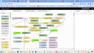
Well come from the problem from a different angle, monitor the volts in Node red and turn on loads so the charging rate is offset by some discharge. Turn off the loads when the voltage drops. Here is my solution for my Sunny Island cutting the PV inverter output by increasing the frequency as the battery gets full.
Attachments
silverstone
Solar Enthusiast
- Joined
- May 3, 2022
- Messages
- 1,050
I tried to setup Nodered in Podman (Docker) but it absolutely doesn't want using bind-mounts. And I HATE Docker/Podman Volumes for backing up ... Yes, I do zfs snapshots and I can send/receive those, but it's still not easy to modify a file in one of those volumes ...Well come from the problem from a different angle, monitor the volts in Node red and turn on loads so the charging rate is offset by some discharge. Turn off the loads when the voltage drops. Here is my solution for my Sunny Island cutting the PV inverter output by increasing the frequency as the battery gets full.
silverstone
Solar Enthusiast
- Joined
- May 3, 2022
- Messages
- 1,050
I used to think the same ... But then I ended up with different VMs and spend most of the time to handle the OS rather than the application customization.My node red is undocked or part of any volume, just runs on a Pi4b as a normal install. KISS rules in my household.
That's why I like the Podman/Docker approach
.Did you put in place a dump load in case of excessive frequency at 50.2 Hz ? Why
? Do you have such sensitive appliances ?Nothing to do with sensitivity, UK is 50htz, the Sunny Island for EU provides a 50htz grid. Any Sunny Boy inverters feeding the Sunny Island are output controlled by frequency so the SI increases the frequency when the battery fills. Once it's 50.2 htz the SI is starting to look to decrease the SB,s output. So if a load is turned on at that point the SI will reduce the frequency, there is a lag, takes 10 secs for some loads to turn on so it can go to 51.5.
silverstone
Solar Enthusiast
- Joined
- May 3, 2022
- Messages
- 1,050
>> so the SI increases the frequency when the battery fills.Nothing to do with sensitivity, UK is 50htz, the Sunny Island for EU provides a 50htz grid. Any Sunny Boy inverters feeding the Sunny Island are output controlled by frequency so the SI increases the frequency when the battery fills. Once it's 50.2 htz the SI is starting to look to decrease the SB,s output. So if a load is turned on at that point the SI will reduce the frequency, there is a lag, takes 10 secs for some loads to turn on so it can go to 51.5.
Not sure I follow you. Each Inverter should have a droop curve whereby Active Power DECREASES if frequency goes above the set point.
And in Island Mode, if you don't need to be compliant with grid codes etc related to voltage/frequency operating ranges, I am not sure it is really a problem.
silverstone
Solar Enthusiast
- Joined
- May 3, 2022
- Messages
- 1,050
By the way ... Even if the wire is shielded, the shield for sure is NOT connected on the ESP32 end.but is should be shielded all the way and the breakout board does not help there ether
its just a guess if its not so much effort for you
maybe also try it without the terminator res
Are the RJ45 jacks in the Deye of the shielded type, i.e. connected to Earth ?
Therefore in the best case you have shielding on one end (Deye Inverter) - effective against electric field only. In the worst, the shield is not earthed at either end, thus completely useless.
CAN Cables exist both in shielded and unshielded variety.
Der_Hannes
Solar Addict
the metal foil shield which covers every pair of leads has nothing to do (as far as i know) with the metal mesh shield around the whole bunch of twisted twisted pairs.By the way ... Even if the wire is shielded, the shield for sure is NOT connected on the ESP32 end.
Are the RJ45 jacks in the Deye of the shielded type, i.e. connected to Earth ?
Therefore in the best case you have shielding on one end (Deye Inverter) - effective against electric field only. In the worst, the shield is not earthed at either end, thus completely useless.
CAN Cables exist both in shielded and unshielded variety.
Only the mesh is connected to the ground clamps of the RJ45 plugs shich might be connected to ground.
The deye inverter is well known to have problems with EMV (EMC?) - so the both "shields" are blocking some of the high frequency emmission the deye is producing
Just keep that in mind - that might be an issue in your case
Similar threads
- Replies
- 2
- Views
- 219
- Replies
- 27
- Views
- 1K
- Replies
- 1
- Views
- 121
- Replies
- 8
- Views
- 977
- Replies
- 19
- Views
- 1K