I believe the substitution has the same name in 1.3.2, so if you can modify your YAML and flash remotely, it should work. Usual risk of remote changes of course.
No, there is a new yambms_cutoff_timer var since 1.4.1.
I believe the substitution has the same name in 1.3.2, so if you can modify your YAML and flash remotely, it should work. Usual risk of remote changes of course.
So would I simply update to latest dev branch or do I modify: yambms_inverter_offset_v or both?No, there is a new yambms_cutoff_timer var since 1.4.1.
Yes, but the inverter offset substitution exists in both 1.3.2 and 1.4.1, doesn't it?No, there is a new yambms_cutoff_timer var since 1.4.1.
Yes, but the inverter offset substitution exists in both 1.3.2 and 1.4.1, doesn't it?
@ChrisG, I would recommend the latest version on Dev in this case. Being on the latest version of @Sleeper85's refinements mean it'll be easier for him to support.
I'll admit, I am not on the YAMBMS version yet.
Thanks. Will clone his current dev repo down later and see if the inverter offset is in 1.4.1. Appreciate all the support. I split one of my 2p16s packs just to test this out. It’s awesome.Yes, but the inverter offset substitution exists in both 1.3.2 and 1.4.1, doesn't it?
@ChrisG, I would recommend the latest version on Dev in this case. Being on the latest version of @Sleeper85's refinements mean it'll be easier for him to support.
I'll admit, I am not on the YAMBMS version yet.
Thanks. Will clone his current dev repo down later and see if the inverter offset is in 1.4.1. Appreciate all the support. I split one of my 2p16s packs just to test this out. It’s awesome.
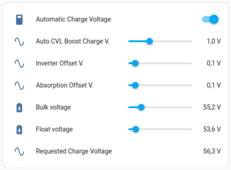
# Inverter Offset V. allows you to correct the inverter charging voltage.
# Requested Charging Voltage = Bulk. V + Inverter Offset V.
yambms_inverter_offset_v: "0.1"
yambms_inverter_offset_v_slider: 'false' # true: the slider is hidden, false: the slider is available
Thanks. Don’t have web enabled in YAML so can’t OTA update it. Won’t be back onsite till later next week.Here is what I use at home.
YAML:# Inverter Offset V. allows you to correct the inverter charging voltage. # Requested Charging Voltage = Bulk. V + Inverter Offset V. yambms_inverter_offset_v: "0.1" yambms_inverter_offset_v_slider: 'false' # true: the slider is hidden, false: the slider is available
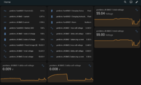
I see the problem between the Bulk Voltage Slider setting and everything else. Here are my metrics:
YamBMS 1 Bulk Voltage: 55.6v (SLIDER)
Inverter Reading: 55.4v
JK BMS 1: 55.44v
JK BMS 1 SOC: 100%
JK BMS 1 Cell Delta: .004
JK BMS 2: 55.43v
JK BMS 2 SOC: 100%
JK BMS 2 Cell Delta: .004
YAMBMS YamBMS 1 Total Voltage: 55.43v
YAMBMS YamBMS1 Battery SOC: 98%
Separate Victron Shunt between Inverter and BMS: 55.43v
Not sure what to change here to get this in sync.
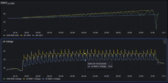
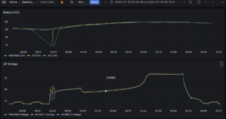
I'll be very interested to see requested charge voltage over time, alongside max cell voltage if you get a chance.
Sadly, this is a case where I'm not sure if I can test effectively with my inverter, it's a bit crap at respecting CVL.
Still working with multiple discharge and charge (90-100%) sessions. @Sleeper85 as you can see I am getting Cut-Off in the charging status. So it seems all conditions are not met for complete charging but the timer kicks in anyway. My Delta is under my trigger amount and voltage is spot on.
View attachment 229700
Ahh ok. So everything is working as expected now. Thanks. I’ve gone through three discharge/charge cycles at this point since my charge SOC is set to 90%. Going to let it continue to run but so far so good.No, it's the opposite.
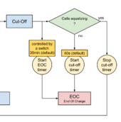
Status Cut-Off all conditions are met to enter the last charging phase before EOC.
yambms YamBMS 1 Warning changed to Alarm
9:42:26 PM - 2 minutes ago
yambms YamBMS 1 Alarm changed to Warning
9:42:26 PM - 2 minutes ago
yambms YamBMS 1 BMS combined changed to 1
9:42:26 PM - 2 minutes ago
yambms YamBMS 1 Cell Count (Σ) changed to 16
9:42:26 PM - 2 minutes ago
yambms YamBMS 1 BMS in alarm changed to 1
9:42:25 PM - 2 minutes ago
yambms YamBMS 1 Errors Bitmask Warning changed to 16384
9:42:25 PM - 2 minutes ago
yambms YamBMS 1 Min Voltage Cell changed to 111
9:42:25 PM - 2 minutes ago
yambms YamBMS 1 Charging Cycles (Ø) changed to 1
9:42:25 PM - 2 minutes ago
yambms Uptime Human Readable changed to 01d 02h 40m 10s
9:42:25 PM - 2 minutes ago
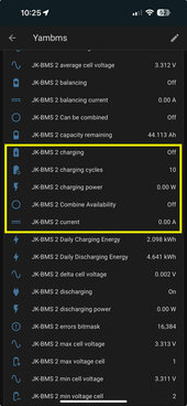
yambms JK-BMS 2 Can be combined turned off
9:42:25 PM - 2 minutes ago
yambms JK-BMS 2 Combine Availability turned off
9:42:25 PM - 2 minutes ago
yambms JK-BMS 2 charging turned off
9:42:24 PM - 2 minutes ago
yambms Uptime Human Readable changed to 01d 02h 40m 05s
9:42:20 PM - 2 minutes ago
float soc = id(${yambms_id}_state_of_charge).state;
float min_cell_v = id(${yambms_id}_min_cell_voltage).state;
float cell_uvpr = id(${yambms_id}_cell_uvpr).state;
if (min_cell_v <= cell_uvpr) return 0; // Real 0% Sending 0%
else if (soc < 1) return 2; // False 0% sending 2%
else if (soc < 99) return soc; // SOC < 99% => Sending BMS SOC
// Useful for some inverters, will not send 100% until charging is complete
else if (id(${yambms_id}_eoc) == true) return soc; // End Of Charge => Sending BMS SOC
else return 98;
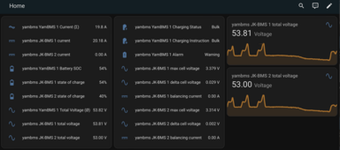
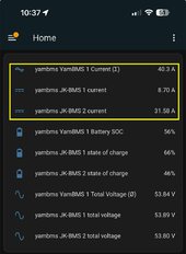
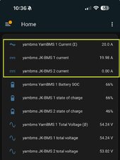
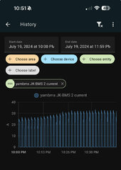
Error bitmask of JK2 is 16,384. Both JKs have Max charge current set to 20a. What I see happening is more than 20a is being sent to JK2 which is causing the alarm and disconnect.
This is an example of a 3 BMS system with 2 BMS in error.
The system continues to operate as long as 1 BMS has no error, the other 2 BMS are decombined.
View attachment 229877
Boxed in orange, these are the instructions sent to your inverter. If you have defined a charge or discharge current of 20A on both BMS you should see 20A or 40A with 2 BMS. Perhaps your inverter does not follow these instructions?
View attachment 229879
# +--------------------------------------+
# | YamBMS Alarm and Warning |
# +--------------------------------------+
# | Errors Bitmask (16bit) |
# +--------------------------------------+
# 0x8B 0x00 0x00: Battery warning message 0000 0000 0000 0000
#
# Bit 0 Low capacity 1 (alarm), 0 (normal) warning
# Bit 1 Power tube overtemperature 1 (alarm), 0 (normal) alarm
# Bit 2 Charging overvoltage 1 (alarm), 0 (normal) alarm
# Bit 3 Discharging undervoltage 1 (alarm), 0 (normal) alarm
# Bit 4 Battery over temperature 1 (alarm), 0 (normal) alarm
# Bit 5 Charging overcurrent 1 (alarm), 0 (normal) alarm
# Bit 6 Discharging overcurrent 1 (alarm), 0 (normal) alarm
# Bit 7 Cell pressure difference 1 (alarm), 0 (normal) alarm
# Bit 8 Overtemperature alarm in the battery box 1 (alarm), 0 (normal) alarm
# Bit 9 Battery low temperature 1 (alarm), 0 (normal) alarm
# Bit 10 Cell overvoltage 1 (alarm), 0 (normal) alarm
# Bit 11 Cell undervoltage 1 (alarm), 0 (normal) alarm
# Bit 12 309_A protection 1 (alarm), 0 (normal) alarm
# Bit 13 309_A protection 1 (alarm), 0 (normal) alarm
# Bit 14 Reserved
# Bit 15 Reserved
#
# Examples:
# 0x0001 = 00000000 00000001: Low capacity alarm
# 0x0002 = 00000000 00000010: MOS tube over-temperature alarm
# 0x0003 = 00000000 00000011: Low capacity alarm AND power tube over-temperature alarm
I didn't follow all of the Discussion (as I told you I'm currently dealing with lots of other Stuff), but what exactly do you do in this Situation, if you continue to Operate ?
- Voltage kept in "safe range" (e.g. "float" 54.0VDC instead of 55.2VDC)
- Temperature kept in "safe range" (e.g. 25-35 °C)
- Current kept in "safe range" (e.g. TOTAL current Reference <= 1 x rated current of each Battery, i.e. you don't "count on the faulty batteries", yet they will each see 1/3 of the total current in this example, so if each battery is rated 100ADC, each will in the end see 33ADC roughly [minus unbalances of course])