diy solar

diy solar

YamBMS JK-BMS-CAN with new Cut-Off Charging Logic (open-source)

YamBMS 1.4.1
  • Rewriting of the alarm system
  • Bug fixes and improvement of the charging logic (new status "Cut-Off ")
  • Icon allocation for each sensor
  • UART and CANBUS !extend ${vars}
  • New sensor YamBMS Delta Cell V
  • Improved Battery SOC logic
  • README update
 
Last edited:
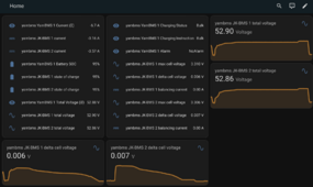
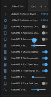
Current version (before post above..lol) of multi-bms code is working great. Regarding OVP and Auto Charge Voltage, if your cells are really out of wack as mine just were from splitting my pack, set the Bulk Voltage to something like 55.6v to get the balancing done. Was taking forever at 55.2v. So far so good, looking forward to next version. Great work by all developers working on this.

1721261184088.png
 
@MrPablo do both of these functions need to be enabled to get my packs back in balance and not keep hitting OVP or just one? I rebuilt the batteries and even with 2A active Balancer, after 10 hours still have a delta. I’m only running with Automatic Charge Current enabled at the moment.

YamBMS 1 Automatic Charge Current
YamBMS 1 Automatic Charge Voltage
I know your balance is a lot better now, so this is a little late.

You can use either or both options.

Voltage control will automatically reduce the requested charge voltage (CVL) sent to the inverter when a cell starts to exceed the bulk target.
That way, the runner cell should be maintained at or near bulk (for example, 3.45v) and the balancer can start to bring up the lagging cells.
Controlling the CVL is the preferred option according to Victron and others, but it depends on how well your inverter behaves.
My Solis inverter is not great at CVL control, so it doesn't work well for me.
You can compare voltage control to cruise control in a car.

Current control will automatically reduce the requested charge current (CCL) sent to the inverter when a cell starts to exceed the bulk target.
This should prevent the runner cell from exceeding the max voltage cutoff, but doesn't maintain it at bulk voltage - instead it should keep it just below max cell voltage.
Current control should work with any inverter that uses CAN control.
You can compare current control to a max speed limiter in a car.

Using both together is like setting the cruise control to 70mph, with a max speed limit of 80mph.
If cruise control (CVL) works correctly with the inverter, the limiter (CCL) will not really kick in.
 
Current version (before post above..lol) of multi-bms code is working great. Regarding OVP and Auto Charge Voltage, if your cells are really out of wack as mine just were from splitting my pack, set the Bulk Voltage to something like 55.6v to get the balancing done. Was taking forever at 55.2v. So far so good, looking forward to next version. Great work by all developers working on this.

View attachment 229376
Out of curiosity, what voltage is your balancer set to turn on?
 
I know your balance is a lot better now, so this is a little late.

You can use either or both options.

Voltage control will automatically reduce the requested charge voltage (CVL) sent to the inverter when a cell starts to exceed the bulk target.
That way, the runner cell should be maintained at or near bulk (for example, 3.45v) and the balancer can start to bring up the lagging cells.
Controlling the CVL is the preferred option according to Victron and others, but it depends on how well your inverter behaves.
My Solis inverter is not great at CVL control, so it doesn't work well for me.
You can compare voltage control to cruise control in a car.

Current control will automatically reduce the requested charge current (CCL) sent to the inverter when a cell starts to exceed the bulk target.
This should prevent the runner cell from exceeding the max voltage cutoff, but doesn't maintain it at bulk voltage - instead it should keep it just below max cell voltage.
Current control should work with any inverter that uses CAN control.
You can compare current control to a max speed limiter in a car.

Using both together is like setting the cruise control to 70mph, with a max speed limit of 80mph.
If cruise control (CVL) works correctly with the inverter, the limiter (CCL) will not really kick in.

Thank you for this nice explanation, to put in the doc.
 
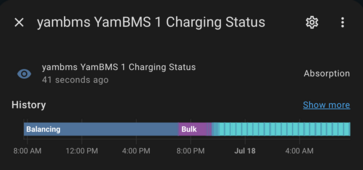
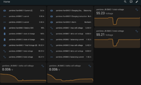
@Sleeper85 and @MrPablo, First note I'm using the version prior to last nights update. Another issue on this last charge cycle...never gets to 100% and starts to discharge. Stays in absorption and never gets to target voltage. No cell runners now so Auto Voltage and Auto Current is turned off. EOC is enabled like it was before. RCV is set to 55.2 but it continues to hover around 55.10 with no current coming in. The only way for me to get it to discharge is to move the bulk voltage slider (assume RCV) below 55.10v manually.
1721303051536.png
1721303079019.png
1721303119361.png
1721303155402.png
 
Last edited:
That might explain why the balancing was taking so long at 55.2v.
For example, if your max cell was being kept at 3.45-3.46v by Auto CVL then the balancer might drop the max cell to 3.445 and balancing stops.
Max cell goes back to 3.45ish, starts again, repeat.

Once you increased to 55.6, the max cell should be kept at 3.475v or so, meaning balancing should be maintained at all points.
Could this be the same issue of my system being stuck in absorption? (post above this)?
 
This is in the base version of code in the Multi BLE YAML:
yambms_absorption_offset_v: '0.1'

I moved the bulk slider to 55.6 and this is far as it goes:
1721309408879.png
 
Last edited:
What is the requested charge voltage reading?
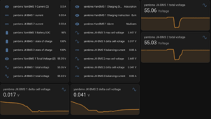
It matches what I have it set to on slider: now 55.6v but as you can see not getting close to it, just stops so basically it never allows a discharge. I even increased lead acid charge voltage inverter to 56v even though I’m using SOC. Had no impact.

1721312784517.png
1721312828539.png


1721312728413.png
 
This is why the current balancing parameters suck in all BMS.
Ideally, we want balancing to happen at the end of a full-charge regardless.

I heard you're trying out the BLE version.

@Sleeper85 @MrPablo
Because Balance parameters are available in BLE all the time,
We can update Balance threshold on the fly near the end of every charge cycle (cut-off)
And then return it to a higher value as soon as the cycle exits so that no balancing takes place.

Ideally, we want the balance switch to turn ON only after cut-off.
As soon as the Battery exits the CutOff stage and enters Float, we want the switch to be OFF until the next Cutoff.
But I don't know how robustly/reliably we can implement this over BLE.
 
YamBMS 1.4.1
  • Rewriting of the alarm system
  • Bug fixes and improvement of the charging logic (new status "Cut-Off ")
  • Icon allocation for each sensor
  • UART and CANBUS !extend ${vars}
  • New sensor YamBMS Delta Cell V
  • Improved Battery SOC logic
  • README update
@Sleeper85 Testing it now :) 33 minutes uptime, so far so good ;)
After your loop time optimisations reducing HA entities number, I went back from:
YAML:
bms_update_interval: 4s' # going below '3s' can cause problems
bms_combine_interval: '2s
to
YAML:
bms_update_interval: '3s' # going below '3s' can cause problems
bms_combine_interval: '1s
and no problems so far.
 
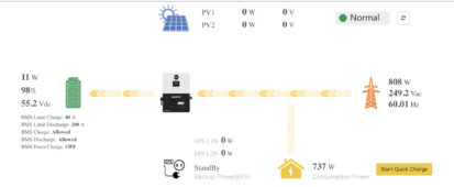
Any remote corrective actions I can take to get this to discharge? Can not get YAML BMS to 100% which would then trigger inverter to discharge.
 
Any remote corrective actions I can take to get this to discharge? Can not get YAML BMS to 100% which would then trigger inverter to discharge.
I'm probably missing something, but why wouldn't your inverter & battery discharge if under 100%? If a load is placed on the inverter, doesn't it discharge to meet it?
 
I'm probably missing something, but why wouldn't your inverter & battery discharge if under 100%? If a load is placed on the inverter, doesn't it discharge to meet it?
It's suck in Grid Bypass/Grid Charging at the moment until it hits 100%. No PV attached when I'm not at the cabin. When BMS hits 100% (on single BMS version) when SOC hit 100% after balancing/RCV hit, it went to discharge. This exact scenario works fine on single BMS code.
1721316212819.png
 
@ChrisG

A very important thing to do is to calibrate the voltage of your BMS according to a specific procedure. I need to make a readme about this, that would be the first thing to do along with checking the BMS settings before starting to use this application.

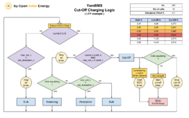
If your inverter charges at 55.2V at the end of charging, the voltage of your pack should reach 55.2V. If this is not the case, it may be due to poor calibration, a voltage drop due to the cables or failure to follow the instructions for your inverter. For this reason there is an inverter offset V. parameter which will be added to the setpoint in order to correct the difference. With a correctly configured system, the end of charge should occur even without using the EOC timer. As long as the charge is not complete the soc will remain at 98% maximum.

Check the diagram below, I reworked and tested this whole part at home yesterday and everything works as expected.


1000015841.png
 
@ChrisG

A very important thing to do is to calibrate the voltage of your BMS according to a specific procedure. I need to make a readme about this, that would be the first thing to do along with checking the BMS settings before starting to use this application.

If your inverter charges at 55.2V at the end of charging, the voltage of your pack should reach 55.2V. If this is not the case, it may be due to poor calibration, a voltage drop due to the cables or failure to follow the instructions for your inverter. For this reason there is an inverter offset V. parameter which will be added to the setpoint in order to correct the difference. With a correctly configured system, the end of charge should occur even without using the EOC timer. As long as the charge is not complete the soc will remain at 98% maximum.

Check the diagram below, I reworked and tested this whole part at home yesterday and everything works as expected.


View attachment 229520
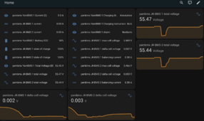
I see the problem between the Bulk Voltage Slider setting and everything else. Here are my metrics:

YamBMS 1 Bulk Voltage: 55.6v (SLIDER)

Inverter Reading: 55.4v
JK BMS 1: 55.44v
JK BMS 1 SOC: 100%
JK BMS 1 Cell Delta: .004
JK BMS 2: 55.43v
JK BMS 2 SOC: 100%
JK BMS 2 Cell Delta: .004
YAMBMS YamBMS 1 Total Voltage: 55.43v
YAMBMS YamBMS1 Battery SOC: 98%

Separate Victron Shunt between Inverter and BMS: 55.43v

Not sure what to change here to get this in sync.
 
Assuming you're using v1.4.1, I think you can just adjust yambms_inverter_offset_v in the main multi-bms YAML.
By default, it's set to zero, in your case you would need to enter 0.2 (55.6-55.4).
 
Assuming you're using v1.4.1, I think you can just adjust yambms_inverter_offset_v in the main multi-bms YAML.
By default, it's set to zero, in your case you would need to enter 0.2 (55.6-55.4).
Running previous version. Will have to wait several days to update when I’m back onsite, unsure if a way to remotely update using ESPHome, have full route VPN connecting to this location.
 
Running previous version. Will have to wait several days to update when I’m back onsite, unsure if a way to remotely update using ESPHome, have full route VPN connecting to this location.
I believe the substitution has the same name in 1.3.2, so if you can modify your YAML and flash remotely, it should work. Usual risk of remote changes of course.
 

diy solar

diy solar
Back
Top