diy solar

diy solar

YamBMS JK-BMS-CAN with new Cut-Off Charging Logic (open-source)

For the moment, the BMS in error are decombined, the load values will be adapted for the number of BMS remaining but if you are in Bulk phase you remain in Bulk, I could change that in the future, to think about.

BMS in error protect themselves by deactivating their charge and discharge switch.
Careful with that though (think about the inrush Current if they reconnect if the Voltage difference is too high, you will need to inhibit that IMHO).

E.g. only allow reconnect on if abs(U_BMS_Healthy - U_BMS_Faulty) < 0.5VDC or something like that ...

(or more complex if you only turn on the Charge OR the Discharge Switch depending on the Situation of course)
 
@MrPablo

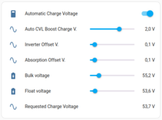
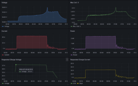
Here is the graph obtained with these parameters without EOC timer enabled.

View attachment 229882

View attachment 229883

View attachment 229884

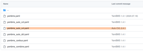
Posted to git, only this YAML has been modified.

View attachment 229885
Thanks @Sleeper85, the data is very useful!

Introducing the boost voltage has resulted in an initial overshoot of max cell voltage. That makes sense, as the PI controller takes time to pull CVL down from the boosted value.
I'll consider what PI parameters might need to be, or if derivative if also required. In an ideal world, there would be minimal overshoot regardless of boost voltage.

Good to see that max cell voltage is maintained at 3.45v afterwards though.
Are you sure you have the anti-windup protection for the integrator Part ? It shouldn't overshoot that much, unless of course the Kp/Ki gains are not properly tuned (or there is a huge delay between measurement and action).

EDIT 1: the anti-windup is to avoid that, in case the output of the integrator saturates, you keep integrating a big error which exceeds the saturation value. As a result, without anti-windup, you will need some time to "empty" your integrator. With anti-windup protection, that doesn't happen.
 
Last edited:
This is an example of a 3 BMS system with 2 BMS in error.
The system continues to operate as long as 1 BMS has no error, the other 2 BMS are decombined.

View attachment 229877

Boxed in orange, these are the instructions sent to your inverter. If you have defined a charge or discharge current of 20A on both BMS you should see 20A or 40A with 2 BMS. Perhaps your inverter does not follow these instructions?

View attachment 229879
The inverter is only sending 20 or 40 but when 40, more than 20 is going to JK2 which is causing it to disable charging. Why would the overall current decrease to match JK1 but not JK2 as outlined in the yellow boxes though. When both are charging it’s allowing 40amp just more than 20a going to the one. I can see that after a few seconds charging JK2 is disabled, decombine happens and overall current drops to 20a and being sent to JK1.
 
Last edited:
The inverter is only sending 20 or 40 but when 40, more than 20 is going to JK2 which is causing it to disable charging. Why would the overall current decrease to match JK1 but not JK2 as outlined in the yellow boxes though. When both are charging it’s allowing 40amp just more than 20a going to the one. I can see that after a few seconds charging JK2 is disabled, decombine happens and overall current drops to 20a and being sent to JK1.
Is that near the top of the charge curve ?

That also happens to me I believe because when one cell shoots up to say 3.52+ VDC, the resistance/impedance of that branch/string/battery increases a lot, so most of the current will go to the other branch/string/battery.

The proper course of Action I believe would be to set the Overall (Total) Charge Current Reference = min(I_BMS_Ref) * NBat, that way you won't have more than 2 x 8.70 ADC in your Example.

At the End of the Day the System is determined by the weakest link, be it max(UBat), min(IBat) ecc.

Of course that by itself might *not* solve all cases of *extreme* unbalance, but it would already be much better than the current situation I believe.

EDIT 1: of course this could be also a tunable parameter for the more adventorous of us, so @Sleeper85 you might also do ITotalChargeRef = k*sum(IBat_Ref_Each) + (1-k)*min(IBat_Ref_Each)*NBat

EDIT 2: @ChrisG I actually had another look at your Pictures, it looks like you are at around 50-60% SOC, assuming that estimate is correct. How is your Cabling ? Do you have EXACTLY the same cross-section, lengths, fuses/breakers on all batteries, from the Inverter/Charger point of view ? Are you sure you do NOT have a bad connection somewhere ?
 
Last edited:
Is that near the top of the charge curve ?

That also happens to me I believe because when one cell shoots up to say 3.52+ VDC, the resistance/impedance of that branch/string/battery increases a lot, so most of the current will go to the other branch/string/battery.

The proper course of Action I believe would be to set the Overall (Total) Charge Current Reference = min(I_BMS_Ref) * NBat, that way you won't have more than 2 x 8.70 ADC in your Example.

At the End of the Day the System is determined by the weakest link, be it max(UBat), min(IBat) ecc.

Of course that by itself might *not* solve all cases of *extreme* unbalance, but it would already be much better than the current situation I believe.
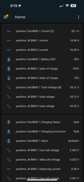
Not even close to top of charge and cells in each pack are balanced. Each BMS set to max 20amp. When combined, 40amp coming in from inverter. JK1 is getting 10amp and JK2 is getting 30amp for some reason. JK2 shuts down charging most likely because is too high amp. Then only 20amp is coming and and only 20amp going to JK1.


Check out this quick video I uploaded. Remember max is 20amp PER BMS for charging:
 

Attachments

  • IMG_5718.jpeg
    IMG_5718.jpeg
    41.2 KB · Views: 2
Last edited:
Not even close to top of charge and cells in each pack are balanced. Each BMS set to max 20amp. When combined, 40amp coming in from inverter. JK1 is getting 10amp and JK2 is getting 30amp for some reason. JK2 shuts down charging most likely because is too high amp. Then only 20amp is coming and and only 20amp going to JK1.

Check out this quick video I uploaded. Remember max is 20amp PER BMS for charging:
Yeah, I checked the picture on my EDIT 2, sorry about that.

What I said about min(I_Bat_Ref) * NBat is still applicable though ... IMHO it should be done like this. Just like UCharge_Ref = min(UCharge_Ref_each) for that matter ...

EDIT 1: and when the current gets in one (or more) batteries gets too high, the requested charge voltage should DROP to avoid trips ...
 
Is that near the top of the charge curve ?

That also happens to me I believe because when one cell shoots up to say 3.52+ VDC, the resistance/impedance of that branch/string/battery increases a lot, so most of the current will go to the other branch/string/battery.

The proper course of Action I believe would be to set the Overall (Total) Charge Current Reference = min(I_BMS_Ref) * NBat, that way you won't have more than 2 x 8.70 ADC in your Example.

At the End of the Day the System is determined by the weakest link, be it max(UBat), min(IBat) ecc.

Of course that by itself might *not* solve all cases of *extreme* unbalance, but it would already be much better than the current situation I believe.

EDIT 1: of course this could be also a tunable parameter for the more adventorous of us, so @Sleeper85 you might also do ITotalChargeRef = k*sum(IBat_Ref_Each) + (1-k)*min(IBat_Ref_Each)*NBat

EDIT 2: @ChrisG I actually had another look at your Pictures, it looks like you are at around 50-60% SOC, assuming that estimate is correct. How is your Cabling ? Do you have EXACTLY the same cross-section, lengths, fuses/breakers on all batteries, from the Inverter/Charger point of view ? Are you sure you do NOT have a bad connection somewhere ?

I just rebuilt the packs. Exact fuses, length and cross-section of cables and torqued properly. If you look at my other recent posts here this works as expected from 90-100%SOC charging range. After rebuild I ran in voltage mode at 90amp total charge (45a per bms) and there were no issues/hotspots with thermal camera on any wires or lugs. Also did a full discharge test at 140a, no problems.
 
I just rebuilt the packs. Exact fuses, length and cross-section of cables and torqued properly. If you look at my other recent posts here this works as expected from 90-100%SOC charging range. After rebuild I ran in voltage mode at 90amp total charge (45a per bms) and there were no issues/hotspots with thermal camera on any wires or lugs. Also did a full discharge test at 140a, no problems.
Well that's good, as a start at least (y) .

Just remember it's a highly nonlinear system, so if at any point of the charge curve the impedance of the string/branch differ, a current unbalance will result. My experience is that mostly happens at the top (or bottom) of the Charge Curve, but maybe one of your Cell is acting in a weird way.

The only thing that software should do IMHO in that case is limit the total current to <= min(IBat_Ref_Each) * Nbat, so that no battery will experience over-current and drop out. Essentially slow-down the charging until the hardware recovers (or you reach the top of the charge curve). You cannot do any magic with batteries hardwired in parallel (unless you want to trigger a disconnect on one of them of course).

EDIT 1: you are NOT using LiFePo4 or ? 20A / BMS seems very low (or do you have these small cylindrical cells) ?

EDIT 2: did you calibrate JK BMS Voltage / Current Measurement ? I didn't calibrate the current measurement but ~ 10-20 ADC difference when my Limit is 100 ARMS / 200Apeak is not a huge deal. In your case it's a HUGE difference ...
 
Last edited:
Well that's good, as a start at least (y) .

Just remember it's a highly nonlinear system, so if at any point of the charge curve the impedance of the string/branch differ, a current unbalance will result. My experience is that mostly happens at the top (or bottom) of the Charge Curve, but maybe one of your Cell is acting in a weird way.

The only thing that software should do IMHO in that case is limit the total current to <= min(IBat_Ref_Each) * Nbat, so that no battery will experience over-current and drop out. Essentially slow-down the charging until the hardware recovers (or you reach the top of the charge curve). You cannot do any magic with batteries hardwired in parallel (unless you want to trigger a disconnect on one of them of course).

EDIT 1: you are NOT using LiFePo4 or ? 20A / BMS seems very low (or do you have these small cylindrical cells) ?

EDIT 2: did you calibrate JK BMS Voltage / Current Measurement ? I didn't calibrate the current measurement but ~ 10-20 ADC difference when my Limit is 100 ARMS / 200Apeak is not a huge deal. In your case it's a HUGE difference ...

I have 3 EVE105 48v packs, only two are connected now. I keep charge/low when not at the inverter/battery location (remote cabin). When on-site I increase charging. Just keeping it safe when not there as this keeps Internet, cameras, fridge freezers running.

Everything was calibrated after I top balanced the packs before putting in service. I have a Victron shunt in the middle of all this validating voltage and current between packs and inverter.

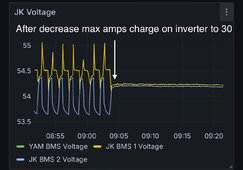
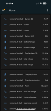
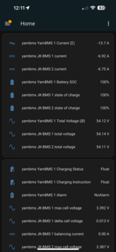
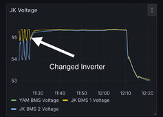
I just figured out a quick work around. Both packs are charging, no warning, no decombining by decreasing the max amp charge INVERTER setting to from 40 to 30amp. This seems to keep the current under the BMS max charge limit for now.
 

Attachments

  • IMG_5720.png
    IMG_5720.png
    182.5 KB · Views: 4
I have 3 EVE105 48v packs, only two are connected now. I keep charge/low when not at the inverter/battery location (remote cabin). When on-site I increase charging. Just keeping it safe when not there as this keeps Internet, cameras, fridge freezers running.

Everything was calibrated after I top balanced the packs before putting in service. I have a Victron shunt in the middle of all this validating voltage and current between packs and inverter.

I just figured out a quick work around. Both packs are charging, no warning, no decombining by decreasing the max amp charge INVERTER setting to 30amp. This seems to keep the current under the BMS max charge limit for now.
I'm still on the previous Software. Is that INVERTER Setting a setting you set on the Inverter itself ? Or it's a "INVERTER Current" Setting you set on the BMS ?
 
I still believe there is something wrong in how there overall reference in computed by the BMS.

I outlined the login that in my opinion should apply.

@Sleeper85: can you comment whether that's already planned or implemented ? Overall (Total) Charge Current Reference = min(I_BMS_Ref) * NBat I mean ...
 
TLDR; set inverter (on inverter itself) max current charging ability to the below Max current of a single BMS to allow charging. Also allows discharging/charging within the parallel packs.

So the only way to get this to work, in my case anyway, is to decrease the inverter charge current setting to the max charging current setting of ONE BMS, in my case 20amp. So the inverter will never send more than 20amps to battery packs. Else it causes a BMS to hit over current protection (happening now on both BMS, flipping back and forth on JK1 and JK2 a few minutes ago). Both BMS hit the same bitmask error of 16384 when they disable charge and decombine.

Worked:
 

Attachments

  • IMG_5723.png
    IMG_5723.png
    182.5 KB · Views: 2
  • IMG_5725.png
    IMG_5725.png
    182.2 KB · Views: 2
  • IMG_5726.jpeg
    IMG_5726.jpeg
    248.4 KB · Views: 2
Last edited:
TLDR; set inverter (on inverter itself) max current charging ability to the below Max current of a single BMS to allow charging. Also allows discharging/charging within the parallel packs.

So the only way to get this to work, in my case anyway, is to decrease the inverter charge current setting to the max charging current setting of ONE BMS, in my case 20amp. So the inverter will never send more than 20amps to battery packs. Else it causes a BMS to hit over current protection (happening now on both BMS, flipping back and forth on JK1 and JK2 a few minutes ago). Both BMS hit the same bitmask error of 16384 when they disable charge and decombine.

Worked:
If you have a static value yeah ... Otherwise adjust to 2 x min(I_Bat_each_pack) dynamically if that's an option for you.

I don't think on my Deye I can even set a Limit ... I think it just uses the references that the BMS communicates to the Inverter. That's why IMHO the BMS should limit to Nbat x min(I_Bat_Ref_each).
 
Are you sure you have the anti-windup protection for the integrator Part ? It shouldn't overshoot that much, unless of course the Kp/Ki gains are not properly tuned (or there is a huge delay between measurement and action).

EDIT 1: the anti-windup is to avoid that, in case the output of the integrator saturates, you keep integrating a big error which exceeds the saturation value. As a result, without anti-windup, you will need some time to "empty" your integrator. With anti-windup protection, that doesn't happen.
Yes, anti-windup is implemented. If you examine the code, you'll see that prev_integral is only updated if the new CVL value is within the upper and lower bound.
If outside that bound, the prev_integral is not updated for use in the next calculation cycle.
These bounds are float voltage or bulk voltage + boost voltage.

Because the CVL has to be reduced by perhaps 2 volts or more if boost is applied, overshoot is pretty likely.
There's always scope to tune the P and I parameters, but introducing derivative control should effectively handle voltage increases as seen in @Sleeper85's example.

Of course, the refresh rate is very important. I run at 1s interval, if using higher values then the PI control will always be slow to react.
 
Last edited:
Interested to hear thoughts if this is a battery, bms or code issue. Never had any problems on single bms version, was quite amazing.
 

diy solar

diy solar
Back
Top