diy solar

diy solar

YamBMS JK-BMS-CAN with new Cut-Off Charging Logic (open-source)

i have the Deye SUN-3.6K-SG03LP1-EU and it works fine with this 3v3 module
Alright, thanks, super. Just ordered a bunch of those from aliexpress... 4 weeks delivery time 😅. In the mean time I guess I need to keep the float voltate at around 56V... Need to lewer it slightly and calibrate the jk bms voltage reading since it hit OVP again (but it's a 0.7v offset measurement error for the whole pack and I trip at 3.60V...)
 
No I don't think it's rocket science, but (unless I was doing something wrong) the messages weren't proper. I don't e. G. Like spaces in names of sensors etc. But it might just be because it was my first attempt.

I must say that Mqtt-Explorer in a docker/podman container on the same host as mosquitto was a great help to understand a bit better how it works.

But the whole thing unauthenticated and unencrypted (or authenticated but not encrypted) still throws me off a bit with Esp32... Or configuring mosquitto and Esp32 to use custom CA and certs (especially using tls v1. 2) I think is unsupported.

And user management within mosquitto (without extra dashboard etc) might also not be so obvious. Not sure if you have reccomendations on that side.

I think I played a lot with several docker containers but never found a proper solution.
im running mosquitto in a docker with authentification but without encryption (only local available
i don´t use spaces or dashes - instead i use underscores

for exploring, i use mxttFX for windows

the user management on mosquitto is a bit tricky and only on CLI - so i just created a bunch of users (set and forget) 🙃
 
Alright, thanks, super. Just ordered a bunch of those from aliexpress... 4 weeks delivery time 😅. In the mean time I guess I need to keep the float voltate at around 56V... Need to lewer it slightly and calibrate the jk bms voltage reading since it hit OVP again (but it's a 0.7v offset measurement error for the whole pack and I trip at 3.60V...)
why charging so high?
i absorb @56.2V and float on 55.2V (most recommended is 55.2/54.xV)
 
why charging so high?
i absorb @56.2V and float on 55.2V (most recommended is 55.2/54.xV)
Because over time I gradually had to lower absorbtion from 55.2v to 55.0v etc. And I still hit OVP at 3.60v.

And it would never balance properly.

And if using the charger connected in parallel to the battery to slowly force a periodic top balance, inverter thinks battery is fully charged and solar power is COMPLETELY ignored.

So basically I was feeding charger - > battery - > inverter with 0% solar during 2 days, even though it was sunny.

So only option is either to periodically set float much higher than required using a very slow ramp every month or so. Or use your code.

But remember... I didn't know about your code until they told me about it in my "Deye bug (or feature)" thread describing the outlined issue.

And maybe it didn't even exist back then when I commissioned my system last September 😉
 
Tomorrow I'm going to lower float and absorbtion a tad to make sure it doesn't hit ovp due to measurement offset etc. But still plan to float at 3.48v per cell or so.

Not many options until I get the can adapter to try your solution.

And anyways the extra victron smartshunt is probably going to be a pain to retrofit on the old batteries (plan to install it in the new ones).
 
just discovered now that this % which my inverter relies on does not update in real-time - making the system drain to 0 % before it realises that it has past the protection mark set on the inverter which then makes it has to recharge to Set inverter SOC every time it drains to BMS SOC.

this is rather annoying as the recharge to Inverter SOC can happen during peak - as was my case today.

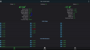
1709847064778.png


Any Ideas?
 
just discovered now that this % which my inverter relies on does not update in real-time - making the system drain to 0 % before it realises that it has past the protection mark set on the inverter which then makes it has to recharge to Set inverter SOC every time it drains to BMS SOC.

this is rather annoying as the recharge to Inverter SOC can happen during peak - as was my case today.

View attachment 200677


Any Ideas?
Which "this %"? Using Sleeper85 code or Der_Hannes? Or the % mode on the Deye inverter instead of voltage mode?
 
just discovered now that this % which my inverter relies on does not update in real-time - making the system drain to 0 % before it realises that it has past the protection mark set on the inverter which then makes it has to recharge to Set inverter SOC every time it drains to BMS SOC.

this is rather annoying as the recharge to Inverter SOC can happen during peak - as was my case today.

View attachment 200677


Any Ideas?
I see your "Cycle Count" is 0.

The "100%" Capacity needs to be "Calibrated" by forcefully recharging the batteries to 100% (and make sure the active balancer kicks in).

I had a similar issue where the voltage would be 51V and the "Capacity" would be 100%, because over several weeks the battery kept charging/discharging but only between say 60% and 80% of nominal capacity.

That's why I feel it's important to make sure that you reach (and keep) a certain equalization/float voltage high enough and for long enough.

The Victron Smartshunt works on a similar principle I believe. IF Battery voltage > threshold && Charging Current < 0.5% (IIRC - Check Andy's Video from Off Grid Garage), then the Smartshunt will report 100%.

If you never fully charge the battery, your SOC "100%" will go low and low each time ....

You might get away in doing it only a few times per week or so. But still, "coulomb counting" (integrating current over time to estimate used/remaining capacity) is very prone to offset error (integrate a few mA of measurement offset current over a few weeks !).

That's why I think both the Victron Smartshunt and the JK BMS (and others) rely on an algorithm based on VOLTAGE > fully charged voltage AND CURRENT < tail current.

EDIT: why do you have a 14s configuration ? That's quite an odd one ...
thanks for your input...

the main issue is that it does not stop at the inverter 15 % set lower SOC.
I am not sure why Sleeper85 did not include the Control of the 100% and 0% SOC into the ESP... it's about the only parameters missing and the most in this aspect. i am sure there is a reason...but if this was and controlled by the ESP this problem would be solved as the inverter talks to the ESP, not the JKBMS.

Do you understand?
You have to asure that you SOC calculatet by the JK BMS is correct at low voltage - otherwise the ESP has no chance to send the right value to the inverter.

If your JK has a soc of 25% for example at the voltage where you decide the battery is at 15% and should stop discharging, the BMS will reset at the UVP settings and drop to 0% in a moment.

Do you have any data historical data to show how the CAN-SoC drops over time? In best case the data would be from the inverter and not from the ESP - maybeyou can provide both?
 
You have to asure that you SOC calculatet by the JK BMS is correct at low voltage - otherwise the ESP has no chance to send the right value to the inverter.

If your JK has a soc of 25% for example at the voltage where you decide the battery is at 15% and should stop discharging.
Do you have any data historical data to show how the CAN-SoC drops over time? In best case the data would be from the inverter and not from the ESP - maybeyou can provide both?
I have decided and i want my 0% JKBMS SOC to be 3.34, My Solis Overdischarge SOC is currently set at 10% - but the issue is there are no arithmetics to my knowledge to tell the Solis that 0% means 10% or to tell the ESP that when BMS says 0% it means 10% (as the Solis only work by the percentage and not the cell SOC set voltages)

When BMS reaches 10 percent how will solis know this - it only knows of BMS's 0% - therefore it will let it drain to 0% and the only thing that tell the Solis to stop is the protection settings set on the BMS....this is a GAP

you understand?

# Edit
The Solis doesn't even know of the BMS 0% it just stops based on the BMS protection settings kicking in....
 
You have to asure that you SOC calculatet by the JK BMS is correct at low voltage - otherwise the ESP has no chance to send the right value to the inverter.

If your JK has a soc of 25% for example at the voltage where you decide the battery is at 15% and should stop discharging, the BMS will reset at the UVP settings and drop to 0% in a moment.

Do you have any data historical data to show how the CAN-SoC drops over time? In best case the data would be from the inverter and not from the ESP - maybeyou can provide both?
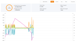
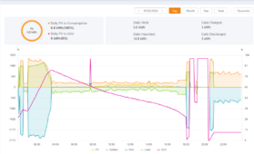
Is this what you are after>?
1709892743332.png

1709892791304.png
 
i have locked my account out by trying the password multiple times, right now using a cookie session - who can unlock it or does it automatically unlock itself after few hours?
 
every time you set the bat capacity, the SOC will be gone

i´m on a hurry leaving for this weekend - maybe could have a look on sunday on your topic

consider to use the full capacity on the BMS (0-100% from UVP to OVP) and then use the SoC from 15-90% in your inverter settings.
Otherwise you will run in the bms protection again and again

(maybe i´m wrong, and i did not get how you want it to be)
But those SOC vertical jumps are non-physical ... Granted he has a relatively small capacity, but it should NOT be a vertical line like that ...

Unless he changed capacity multiple times (but is it reset to 100% SOC when you change the capacity setting in the JK BMS app ???).

The SOC jumping to zero could be a result of a cell hitting UVP indeed.

Another possibility is that you have a VERY UNBALANCED pack. SOC is determined by the LOWEST SOC / capacity cell. That's the one that will hit OVP respectively UVP first, all other things being equal.

So maybe it's linear until 25% then all of a sudden one cell drops (lower steep SOC vs voltage characteristic) ?

It's still IMHO a sign that the cell was NOT left in a high SOC/voltage so that the algorithm could reset. As I said, I experienced this one time as well, whereby the "real" SOC would drop over time, while the "indicated" SOC would still show fully charged.

Did you try to do a Change of Capacity (again ?), FULLY charge (I don't mean necessarily more than 3.50-3.55 V/cell, that should be enough), let all cells get balanced (again, at 3.50-3.55 V/cell, for me it took 36 hours), then let it start to operate.
 
Last edited:
every time you set the bat capacity, the SOC will be gone

i´m on a hurry leaving for this weekend - maybe could have a look on sunday on your topic

consider to use the full capacity on the BMS (0-100% from UVP to OVP) and then use the SoC from 15-90% in your inverter settings.
Otherwise you will run in the bms protection again and again

(maybe i´m wrong, and i did not get how you want it to be)
Thats what i have done

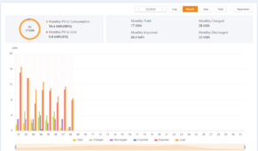
1709906542351.png
 
As a test - Right now its discharging
you would expect that it stops at 10% Or at least when the cell voltage reaches the cut of point set on th eBMS (3.34 0% SOC and even 3.33 UVP )

but it goes past it, bcos i think the current drives the voltage and therefore we do not know the true voltage when the current is flowing

1709906985002.png
 

diy solar

diy solar
Back
Top