chaosnature
New Member
- Joined
- Sep 15, 2022
- Messages
- 527
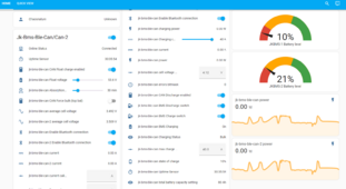
From 11% it will just skip straight to 0 and starts to attempt to recharge back to 10%
3.33 V / cell UVP ???As a test - Right now its discharging
you would expect that it stops at 10% Or at least when the cell voltage reaches the cut of point set on th eBMS (3.34 0% SOC and even 3.33 UVP )
but it goes past it, bcos i think the current drives the voltage and therefore we do not know the true voltage when the current is flowing
View attachment 200819
Lithuim ....3.33 V / cell UVP ???
You are NOT using LiFePo4 / LFP then !
Of course you can hit UVP during a "load step" but for LiFePo4 UVP is typically 2.50 V / cell (absolute minimum) to 2.7 V - 2.8 V / cell.
OK and are you sure the inverter is correctly set up ?Lithuim ....
# Data Sheet - Operating Voltage
46v (3.28) to 57v (4.07)
Up date - This time it stopped (Expected Behaviour )As a test - Right now its discharging
you would expect that it stops at 10% Or at least when the cell voltage reaches the cut of point set on th eBMS (3.34 0% SOC and even 3.33 UVP )
but it goes past it, bcos i think the current drives the voltage and therefore we do not know the true voltage when the current is flowing
View attachment 200819

Inverter necessary setup screenshot is above in previous post.3.33 V / cell UVP ???
You are NOT using LiFePo4 / LFP then !
Of course you can hit UVP during a "load step" but for LiFePo4 UVP is typically 2.50 V / cell (absolute minimum) to 2.7 V - 2.8 V / cell.
Well if your capacity is wrongly set the SOC value is wrongly calculated.Up date - This time it stopped (Expected Behaviour )
View attachment 200820
so its a hit and miss...
Up date - This time it stopped (Expected Behaviour )
View attachment 200820
so its a hit and miss...

No,Well if your capacity is wrongly set the SOC value is wrongly calculated.
Then you hit UVP before inverter/bms says SOC too low ...
Your SOC was not 0 at 3.34V.No,
The 0% SOC is 3.34
UVP is 3.33
it should stop at 3.34
and i use UVP as backup so it does not fall too below the inverter 10% Overdischarge SOC
Nothing to tell the inverter it has reached 10% , no link, which is my point ....the link would have been - in the YAML script some little arithemtics to trick the inverter into thinking its at 15% when it reaches BMS 0% SOC.Then you hit UVP before inverter/bms says SOC too low ...
I said it before and say it again: "coulomb counting" / integration. Your SOC is NOT determined based on the voltage. Your 100% SOC is defined after equalization at the highest operating voltage for enough time as required by your cells to balance.Your SOC was not 0 at 3.34V.
I said it before and say it again: "coulomb counting" / integration. Your SOC is NOT determined based on the voltage. Your 100% SOC is defined after equalization at the highest operating voltage for enough time as required by your cells to balance.
Then your SOC gets updated based on a balance of current in / current out of the battery.
In mathematical terms:
SOC(t + dt) =SOC(t) + 1/C * I(t) * dt
So if C is wrong so is the rate of change of your SOC ...
I said it before and say it again: "coulomb counting" / integration. Your SOC is NOT determined based on the voltage. Your 100% SOC is defined after equalization at the highest operating voltage for enough time as required by your cells to balance.
What you seem to be asking is more of an alternate voltage-based minimum (with some time filtering of course) that would correspond to your theoretical 0% SOC.O.k i hear you ... i was with the impression the % is affected by the margin between 0% SOC and 100% SOC...i can swear i have seen it adjust when i adjusted the SOC upper and lower end...
Also - i kind of suspected this was the case - so i have been playing aorund with the Ah to try and get the Batt 1 align with Batt-2, but have not succeeded yet, sometimes it batches then after some time it lags .....i guess this is the draw back with no RS485 comunication between both setup.Your SOC was not 0 at 3.34V.
I said it before and say it again: "coulomb counting" / integration. Your SOC is NOT determined based on the voltage. Your 100% SOC is defined after equalization at the highest operating voltage for enough time as required by your cells to balance.
Then your SOC gets updated based on a balance of current in / current out of the battery.
In mathematical terms:
SOC(t + dt) =SOC(t) + 1/C * I(t) * dt
So if C is wrong so is the rate of change of your SOC ...
I think MQTT is fine. You are refreshing your SOC at 5s intervals max. That is plenty. You have 3x less capacity per battery bank than me, but it takes several MINUTES to even have 1% SOC variation to me (and I use/have more power). I still suspect you didn't top balance the pack and/or leave it at high voltage enough for the SOC to correctly "reset" to 100%.Also - i kind of suspected this was the case - so i have been playing aorund with the Ah to try and get the Batt 1 align with Batt-2, but have not succeeded yet, sometimes it batches then after some time it lags .....i guess this is the draw back with no RS485 comunication between both setup.
I think MQTT is fine. You are refreshing your SOC at 5s intervals max. That is plenty. You have 3x less capacity per battery bank than me, but it takes several MINUTES to even have 1% SOC variation to me (and I use/have more power). I still suspect you didn't top balance the pack and/or leave it at high voltage enough for the SOC to correctly "reset" to 100%.
I still suspect you didn't top balance the pack and/or leave it at high voltage enough for the SOC to correctly "reset" to 100%.
It's also possible your batteries have different capacities. Or you have a cell that "stands out" in terms of low(er) capacity.
Remember to leave them at the high voltage for at least 12-24 hours. Otherwise the lowest-voltage cell will SKEW the whole thing.Yup - You might be right there, bcos i have not been able to get them both to absolute 100% yet
90% batt-1 and batt -2 maybe 80
The average doesn't matter much if your system is not linear at all. Look at all your 2 packs x 14 cells individual voltages. And ... again ... at the TOP of the charge curve with enough voltage for enough time.They are both built out of same model same capacity battery GBLI5001
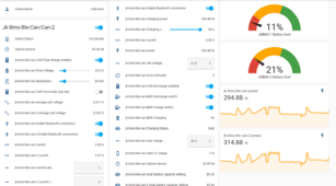
but i suspect one performs more that the other...but the average voltage are always matched, if you look at the screenshot i sent..
Approximately the same length - yesThe average doesn't matter much if your system is not linear at all. Look at all your 2 packs x 14 cells individual voltages. And ... again ... at the TOP of the charge curve with enough voltage for enough time.
What about cable lengths ? Are you sure they are the same to both batteries ? That would always pull more current from one battery, then the other would discharge into the first one.

I will....Remember to leave them at the high voltage for at least 12-24 hours. Otherwise the lowest-voltage cell will SKEW the whole thing.
Lithium is not as flat as LiFePo4, but I believe you could have the same problem if your voltage was not applied high enough for long enough.
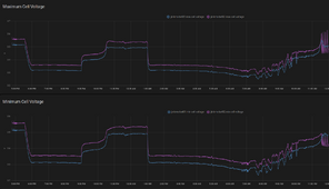
Look more at the cells individual voltages during equalization. Remember, your "Whatever" SOC value is totally irrelevant, if (and before) the pack was not fully charged & balanced.


If the Solis Overdischarge SOC is set to 10%, then as soon as the BMS reports 10% to the Solis, use of the battery for power by the Solis should stop. Are you saying that is not happening?I have decided and i want my 0% JKBMS SOC to be 3.34, My Solis Overdischarge SOC is currently set at 10% - but the issue is there are no arithmetics to my knowledge to tell the Solis that 0% means 10% or to tell the ESP that when BMS says 0% it means 10% (as the Solis only work by the percentage and not the cell SOC set voltages)
When BMS reaches 10 percent how will solis know this - it only knows of BMS's 0% - therefore it will let it drain to 0% and the only thing that tell the Solis to stop is the protection settings set on the BMS....this is a GAP
you understand?
# Edit
The Solis doesn't even know of the BMS 0% it just stops based on the BMS protection settings kicking in....
It was not happening ... i am gonna keep an eye on it and see if it goes wrong again.......and report back hereIf the Solis Overdischarge SOC is set to 10%, then as soon as the BMS reports 10% to the Solis, use of the battery for power by the Solis should stop. Are you saying that is not happening?
My bet is that your initial capacity was too high thus the JK BMS "thought" it still had "enough" SOC while in reality it was just about to drop off a cliff (UVP). Or, again, algorithm not properly reset due to insufficient voltage / time at the high end. Or balancing issues.It was not happening ... i am gonna keep an eye on it and see if it goes wrong again.......and report back here


