diy solar

diy solar

The Electrodacus SBMS thread (SBMS0, DSSR50, etc)

Hey, following an email from Dacian (about wiring a shore charger in parrallel with a DSSR20) I am questioning my understanding of EXT IO wiring...

Dacian explains that the DSSR is wired such that EXT IO4- goes to the battery pin on the DSSR 20, and the EXTIO4+ goes to the battery (via a 4.7kohm resistor)... Ok, fair enough... Glad I checked that :)

Does this then mean that when wiring the EXTIO3 circuit I need to connect EXTIO3 to batt +ve and then EXTIO3- to my load switches (Victron BP, and an SSR for my inverter)?

I might well be having a brain fart here... but I can't seem to see anything specific about this wiring in the manual..

I would email Dacian again, but I thought it might be better to raise the issue here so other newbies might learn from it :)

Cheers :)
Maybe I'm misunderstanding your question, but if you're wondering where to stick the +/- ends of those EXTIOs, you can see where I have 'em in my diagram (click the pic in this link).
 
Thanks for your reply... I re-watched Will's video on this... which clears up my question about EXTIO4...

What threw me was Dacians reply regarding the wiring of a dssr20 " The DSSR20 requires a +battery voltage to the batt remote port through a 4.7kOhm resistor https://electrodacus.com/DSSR20/DSSR20.pdf page 7 figure b) "

Do you have your DSSR's setup in this fashion?

Thanks again :)
Ahhh. Ok, that explains it. Do you have the new DSSRs that can divert? If you do, then yes, you need to add resistor if you're not using his new DEXT16 to connect DSSRs to battery. Need to dig into that new manual a bit to ID exactly how that all works now, but he's omitted the wires from the DEXT16 to the battery in the diagram on page 5 to give you the whole picture of how to use DEXT16 and probably ought to add a 2nd diagram showing the resistors you need to add to the DSSR connection to battery if you DON'T need the DEXT16. Hope that makes sense. I'd just ask him for the later diagram if you're not using DEXT16 but, if it were me, I'd just plop down the $14 to get the DEXT16 and make sure you connect the battery to that (wires missing in diagram on page 5 that go from DEXT16 to battery ... the 2 left-most posts on the DEXT16 pic on page 5 but I'd ask him to confirm that's correct, given the diagram is not explicit on this).
 
One more quick one... I notice you're using IO5 to control your dc/dc converter. Was that complex to setup? I was planning to run both my inverter and my victron sbp (for switching 24v loads) from the same IO3

I'm assuming you've decided to use IO5 so that you can set different thresholds for it?

Cheers
 
  • Like
Reactions: Dzl
One more quick one... I notice you're using IO5 to control your dc/dc converter. Was that complex to setup? I was planning to run both my inverter and my victron sbp (for switching 24v loads) from the same IO3

I'm assuming you've decided to use IO5 so that you can set different thresholds for it?

Cheers

Also curious to learn what went into this decision, and what extra capabilities/granular control it allows.
 
I'm sure @Dhowman will comment on his specific design choice on EXTIO5.

In general any of the EXTIO lines are just optocoupled switched outputs than can be configured to trigger on different events. By convention, Dacian recommends use of EXTIO3 for loads/LVD and EXTIO4 for charging/HVD.

But that doesn't mean you can connect EXTIO3, for example, to multiple load devices in parallel. While each of the devices individually can be controlled by jumpering the two remote control terminals with a switch, internally they may be different. For example, one may be 12V pull-up and one 5V pull-down and connecting both to the same optocoupler would not work. Having a separate optocoupler for each device enables handling those differences. Using EXTIO5 just enables another independent optocoupler for a separate load device like a 24/12 DC-DC converter, that can also be driven by LVD as is EXTIO3.
 
Came across this little footnote in the SBMS0 manual.
*the Over current settings are not used for SBMS0.

Can anyone confirm whether the SBMS has any sort of over-current protection, short-circuit protection, or over-current warning/alarm?

Its not in the current path, so obviously it doesn't need overcurrent protection in the same sense that a FET based inline BMS does. But I'd still like to understand what its capable of.

Along the same lines, I thought I remembered hearing the SBMS0 is capable of SOC based (and opposed to or in addition to voltage based) disconnect thresholds, can anyone confirm, couldn't find anything in the manual?
 
Came across this little footnote in the SBMS0 manual.


Can anyone confirm whether the SBMS has any sort of over-current protection, short-circuit protection, or over-current warning/alarm?

Its not in the current path, so obviously it doesn't need overcurrent protection in the same sense that a FET based inline BMS does. But I'd still like to understand what its capable of.

Along the same lines, I thought I remembered hearing the SBMS0 is capable of SOC based (and opposed to or in addition to voltage based) disconnect thresholds, can anyone confirm, couldn't find anything in the manual?
No OCP, those fields in the SBMS0 are grayed out.

Yes you can do SOC based disconnect. Dacian himself doesn't like or recommend that, he prefers they just drive alarms. Since SOC is a derived number that can be wrong based on user error and other factors. But the SBMS0 does let you configure it.
 
  • Like
Reactions: Dzl
So my SBMS40 has sat in a box for over a year awaiting progress on the project I intended for it. Which is finally moving ahead and taking shape. But I'm a few models behind the rest of y'all. ;)

Maybe someone can help with some questions (I feel I've annoyed Dacian enough with my endless emails):

1) Has anyone figured out a way to rig up a remote wired display? I know you can do the whole wifi AP and web page thing on a phone. I'd prefer something simpler, wired, that doesn't require a phone. MT50, RasPi, Arduino, whatever.

2) I know there's connectors for an external thermistor but I'm getting conflicting information about how it supposed to or can be used. Dacian himself is inconsistent, calling it the battery temperature in some models and then just "external temp" in others. What actionable things can the SBMS be set to do in response to the temp readings off this probe?

3) Does the SBMS40 require a heatsink? He mentions it in the manual but the SMBS40 is unique from the other models as it does not have a metal backing. So if you actually attached a heatsink, you'd be trying to pull heat just off the PCB and not actual metal. Which doesn't seem like it'd work very well.

3b) Anyone who HAS attached a heatsink to any model SBMS: you have screw holes that you could attach the heatsink with, but then there's nothing to use to attach the SBMS itself to something. Anyone come up with an ingenious solution? Best I can come up with is cutting out the back part of the mounting board to be just shy of the dimensions of the SBMS and leaving material beneath the screw holes. Then finding a heatsink that will fit within the cut-out so it protrudes off the back. Heatsink would have to be attached with thermal glue or tape since you're using the holes to attach the SBMS to the board.

4) I'm really struggling with the inability to put proper catastrophic breakers/fuses in the proper places for this, given its limitations (unique to the models before the SBMS0, which doesn't have this problem). I totally get why the battery must not get disconnected while the 10-pin BMS connector is connected, but it still doesn't leave me with warm fuzzies from a safety standpoint of the overall system. What have others done? Put in a fuse anyway as the last-resort safety and just accept that they'll also fry their $200+ SBMS as a result if that fuse pops?

5) I've read and re-read the posts in this thread on the topic, but I just don't feel I understand the final answer. just how does a SBMS handle voltage coming off the panels of perhaps 17-18VDC when the batteries only want about 4VD and can get damaged by more? I'm sure the issue is solved, I just don't understand how.

6) I have some ideas on how one might use EXTIO5 and IO6 to trigger external LEDs for say "100% SOC" and "0% SOC" but I can't actually test this until some time in the future. Has anyone done something similar with any model SBMS?
 
Last edited:
I thought I'd as here... as I feel guilty emailing Dacian all the time (he replies so fast, it makes me feel bad for pestering).

I've got the meanwell rsp750-27v charger working with my SBMS0, which is awesome. Dacian was a great help in figuring out how to get the charger to behave.

I've ordered an optocoupler ssr (specifically a crydom DC60S7) for switching the remote on/off on my inverter (EPEVER SHI3000) . Am I right in thinking that I just wire up EXT IO3+ to the +ve input on the ssr, and EXT IO3- to the -ve input on the SSR? Sorry if this sounds brainless, but I'm prone to making dumb mistakes at times... The SBMS0 will then switch the SSR so it will output a signal to the inverter remote port right?

Cheers,

James
 
I’m new to this forum but have been running Dacian’s SBMS in my RV for 3 + years.

So my SBMS40 has sat in a box for over a year awaiting progress on the project I intended for it. Which is finally moving ahead and taking shape. But I'm a few models behind the rest of y'all. ;)

Maybe someone can help with some questions (I feel I've annoyed Dacian enough with my endless emails):

1) Has anyone figured out a way to rig up a remote wired display? I know you can do the whole wifi AP and web page thing on a phone. I'd prefer something simpler, wired, that doesn't require a phone. MT50, RasPi, Arduino, whatever.
I wanted this at one point but the system is so solid I only check the SOC every couple days when we’re on the road and never think about it otherwise.

2) I know there's connectors for an external thermistor but I'm getting conflicting information about how it supposed to or can be used. Dacian himself is inconsistent, calling it the battery temperature in some models and then just "external temp" in others. What actionable things can the SBMS be set to do in response to the temp readings off this probe?
I have a thermocouple on one of my battery cells. It disables charging when very cold

3) Does the SBMS40 require a heatsink? He mentions it in the manual but the SMBS40 is unique from the other models as it does not have a metal backing. So if you actually attached a heatsink, you'd be trying to pull heat just off the PCB and not actual metal. Which doesn't seem like it'd work very well.
The need for a heat sink is based how much current you’re driving in AND out. Dacian has the resistance levels of each circuit in the manual. Figure out how many watts you need to dissipate to find out whether you need a heat sink.
The MOSFETs are mounted on an aluminum board and not fiberglass so dissipation is efficient.

3b) Anyone who HAS attached a heatsink to any model SBMS: you have screw holes that you could attach the heatsink with, but then there's nothing to use to attach the SBMS itself to something. Anyone come up with an ingenious solution? Best I can come up with is cutting out the back part of the mounting board to be just shy of the dimensions of the SBMS and leaving material beneath the screw holes. Then finding a heatsink that will fit within the cut-out so it protrudes off the back. Heatsink would have to be attached with thermal glue or tape since you're using the holes to attach the SBMS to the board.

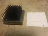
I sized my heatsink for a large discharge load of about 100A and 80A (60 from alternator + 20 from solar) of charging at the same time. In reality i’ve never had more than about 25A of loads since my inverter power doesn’t pass through the SBMS-100

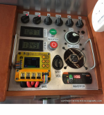
The 3rd post in this thread has pics of my heat sink and shows the mounting screws I used. The 2nd post is my control panel: https://groups.google.com/forum/m/?...er#!msg/electrodacus/FUEYKk5G6E8/KNKDiwmyAAAJ

4) I'm really struggling with the inability to put proper catastrophic breakers/fuses in the proper places for this, given its limitations (unique to the models before the SBMS0, which doesn't have this problem). I totally get why the battery must not get disconnected while the 10-pin BMS connector is connected, but it still doesn't leave me with warm fuzzies from a safety standpoint of the overall system. What have others done? Put in a fuse anyway as the last-resort safety and just accept that they'll also fry their $200+ SBMS as a result if that fuse pops?
In the earlier BMSs like ours, if you disconnected the battery positive while the sun was shining on your arrays, the solar arrays would perform the electrical equivalent of water hammer in your pipes when you turn off a faucet really fast and fry one of the ICs. To get around this, I believe Dacian recommends adding a zener diode between the pos and neg wires to dump the panel’s inductance induced voltage spike. This may permit the use of a fuse, but I’m not certain.

Fusing is intended to protect wiring. I have fuses on all my loads so the only way I could over current the batt+ wire is if it shorted to ground. I have that wire secured every few inches so there isn’t much opportunity for abrasive wear on the cable insulation and I also have most of that wire run in a fabric sleeve, split loom, or both.

If the negative wire is removed, all loads will try to use the cell sensing wires for their return path and fry your SBMS.

5) I've read and re-read the posts in this thread on the topic, but I just don't feel I understand the final answer. just how does a SBMS handle voltage coming off the panels of perhaps 17-18VDC when the batteries only want about 4VD and can get damaged by more? I'm sure the issue is solved, I just don't understand how.
The LiFePO4 battery has a very low internal resistance so it’s not possible for the charge voltage to be higher than the battery voltage. The charging voltage will always sag down to the battery voltage. An exception might be if you had had a MASSIVE array and could drive 10C or 20C or more of current. Since you have a SBMS-40, you don’t have enough power to worry about this.

6) I have some ideas on how one might use EXTIO5 and IO6 to trigger external LEDs for say "100% SOC" and "0% SOC" but I can't actually test this until some time in the future. Has anyone done something similar with any model SBMS?
You can’t have a 0% SOC LED because there would be no current to drive it. Try 20% instead. :p.

When charging from my alternator I don’t like how the early SBMSs turn the charging on and off several times per minute to keep the battery topped off. The 60A battery to battery load slams my alternator too often for my comfort so I designed a latching circuit to take both these outputs and turn the alternator on at <70% charge and off again at >95% charge.

If you’re going to drive LEDs directly, and not isolated, you will be limited to 20mA so you may need to add a resistor in-line with your LED.

Edit to clean up Bb code and add pics:1599973088898.png
1599973182852.jpg
1599973261991.jpg
Since that schematic was finished I added an additional switch and a Bogart charge controller(minus the trimetric) to charge the chassis battery from the solar when boondocking for extended periods.
 
Last edited:
We just had a few emails exchange where I asked him directly why the percentages in the video don't match what I calculated and he avoided the question by using the reverse formula to show the 25.6 % of the table was correct and saying that anyway it's irrelevant as it's for a -30 °C ambient temp and it's for the 72 cells panel (I used the 239/321 W example).
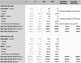
I redid all the math; see screen shot. I COMPLETELY agree he used the wrong denominator, but I agree with Dacian's conclusions. If you ignore the totally unrealistic 5C and 25C figures, the differences are negligible. Plus, where there's minimal benefit of MPPT, he recommends direct charging for LiFePO4 cells, WHICH YOU CAN DO W/O HIS PRODUCTS. And where MPPT shines, with 72 cell panels, he suggests using your judgment on whether to direct connect and add an extra panel. I don't see a problem here other than a math formula error.
Screen Shot 2020-09-14 at 2.01.58 AM.png
Yeah... excepted the problem is the same for all the percentages, whatever the temp or the panel.

I don't like when someone is trying to BS me, but oh well, I'm more disappointed than anything else, no point continuing. So I'll stop writing about the SBMS.

@BiduleOhm Sounds like you already have your mind made up, and I read through the whole thread to make sure no one had addressed this to your satisfaction. I know @Dhowman tried too. I get similar numbers as you using the Solar BMS / DSSR setup using the SBMS/DSSR as the denominator. I get very close to Dacian's figures if you use the MPPT power as the denominator and 97% as the efficiency as quoted by @Dhowman (probably rounding errors somewhere).

If you ASSUME evil intent, then he IS trying to fudge the numbers to sell a few more $37 DSSR20's to a couple dozen people, his scam is pretty pathetic and small fry, plus he's sabotaging himself by stating in MANY places he does NOT recommend using two of his SBMS's for 48V systems.

If you DON'T assume evil intent, then he's just a nice guy with a different way of looking at things making amazing things at VERY reasonable prices. If you prefer the conventional wisdom, go ahead and do it. But don't make an innocent person into a scam artist based on one math error copied and pasted into a spreadsheet.

I'm not convinced I'm moving away from MPPT, but Dacian makes a really good case for it; I have 60 cell panels and a Victron SmartSolar 100/50; I don't think I'll get my money's worth with it.
 
I'm not convinced I'm moving away from MPPT, but Dacian makes a really good case for it.

This right here ^ is how I feel as well (though as I already mentioned in the other thread, I think you are misunderstanding the point he makes about 60 cell panels)

Personally, I think he may be overstating the case to a degree, and I'm skeptical that the whole rest of the industry got it wrong, but he does make a compelling argument and the logic seems mostly sound (with a few caveats). Its a complicated subject, and I plan to do my best to keep an open mind until more experiments or at least experiences begin to trickle in, or until I pony up the cash to do my own testing. I do want him to be right because it would be cheap and easy to go with DSSR20's instead of MPPT, and I like the simplicity.

The biggest outstanding questions for me is how would the two compare over the full range of seasons and conditions, and in partial shade conditions.
 
I redid all the math; see screen shot. I COMPLETELY agree he used the wrong denominator, but I agree with Dacian's conclusions. If you ignore the totally unrealistic 5C and 25C figures, the differences are negligible. Plus, where there's minimal benefit of MPPT, he recommends direct charging for LiFePO4 cells, WHICH YOU CAN DO W/O HIS PRODUCTS. And where MPPT shines, with 72 cell panels, he suggests using your judgment on whether to direct connect and add an extra panel. I don't see a problem here other than a math formula error.
View attachment 22672


@BiduleOhm Sounds like you already have your mind made up, and I read through the whole thread to make sure no one had addressed this to your satisfaction. I know @Dhowman tried too. I get similar numbers as you using the Solar BMS / DSSR setup using the SBMS/DSSR as the denominator. I get very close to Dacian's figures if you use the MPPT power as the denominator and 97% as the efficiency as quoted by @Dhowman (probably rounding errors somewhere).

If you ASSUME evil intent, then he IS trying to fudge the numbers to sell a few more $37 DSSR20's to a couple dozen people, his scam is pretty pathetic and small fry, plus he's sabotaging himself by stating in MANY places he does NOT recommend using two of his SBMS's for 48V systems.

If you DON'T assume evil intent, then he's just a nice guy with a different way of looking at things making amazing things at VERY reasonable prices. If you prefer the conventional wisdom, go ahead and do it. But don't make an innocent person into a scam artist based on one math error copied and pasted into a spreadsheet.

I'm not convinced I'm moving away from MPPT, but Dacian makes a really good case for it; I have 60 cell panels and a Victron SmartSolar 100/50; I don't think I'll get my money's worth with it.

As said I'll not write more about that as I don't want more drama or anything, that wasn't the point. The point was to use the proper numbers and not the misleading ones, which you've done for all of us, and I thank you for that ;)

This right here ^ is how I feel as well (though as I already mentioned in the other thread, I think you are misunderstanding the point he makes about 60 cell panels)

Personally, I think he may be overstating the case to a degree, and I'm skeptical that the whole rest of the industry got it wrong, but he does make a compelling argument and the logic seems mostly sound (with a few caveats). Its a complicated subject, and I plan to do my best to keep an open mind until more experiments or at least experiences begin to trickle in, or until I pony up the cash to do my own testing. I do want him to be right because it would be cheap and easy to go with DSSR20's instead of MPPT, and I like the simplicity.

The biggest outstanding questions for me is how would the two compare over the full range of seasons and conditions, and in partial shade conditions.

There's a big reason pretty much everyone use MPPTs, and it's not in the table which compares only SCCs because it concerns the wires. When you start talking bigger installs than RVs (i.e. longer wires and/or higher powers) it's not practical and especially not economical to use PV arrays with the same voltage as the battery as then you need incredibly thick wires to have the same losses than a higher voltage installation with MPPTs.

If we take the example of my old estimation for what I'll need (it's actually undersized, I'll probably need more) we're talking 16 kW of PV panels. I'll use 48 V batteries as it's the higher we can use without being in the extremely dangerous voltages zone. So 16000 / 48 = 333 A so the Dacian solution means I need to send more than 300 A at a 20-30 m distance... <-- edit: it's actually twice as worse as you can't use 48 V with the SBMS, only 24 V, which means more than 650 A...

Compare that with a 400 V PV system (probably what I'll chose, maybe 500 V even) and you're down to 40 A which is totally reasonable given the distance. Even a 250 V system would be ok (64 A) if you don't want go to high on the voltage.

I don't even need to do the math to know the cost of 300 A wires (or busbars more realistically, especially to be under 3 % losses) will be astronomical and would pay for a lot of MPPT controllers.

It's even more important in my case where I don't have infinite real estate to put panels to compensate higher losses of a low voltage system (and even then you need to pay for the panels too...)

Also you need to add fuses/breakers, disconnects, etc... which would again be a lot more expensive for 300 A rather than 40 A (and you would need a lot more of them because all your panels would be in parallel and each string need one).

When you compare system efficiencies you need to compare the whole system efficiencies, there's no point comparing just a component (the SCC in this case), and it's the same with cost.
 
Last edited:
This thread has taken on a religious fervor which is why I avoided joining this site.

Dacian’s argument is based on economics for his use case. And he starts with the tenet that panels are now so cheep (under $0.65/watt) that maximum efficiency is no longer a primary design driver and that 60 cell panels, when paired with 8 cell LiFePO4 batteries, are very efficient (good enough) and if you need more power you can always add another panel.

This isn’t possible for RV users and he’s argued with me that using the alternator isn’t cost effective. True enough, but those of us with RVs don’t care about 30 year amortized costs or we wouldn’t own RVs. We just want full batteries when we reach our destination or after 3 days in the rain and alternators can charge my batteries faster than the sun ever could.

He readily admits MPPT makes sense in residential grid tied systems where array size is limited and every watt equals $$$, thus the payback on the MPPT can be justified.

His more detailed argument is that off grid users aren’t generally array limited and the benefits of his system are in the reduced fusing costs, safety of lower voltages, and reliability of being able to stick with solid state controllers with life-spans >30 years. MPPT requires the use of electrolytic capacitors which crap out after about 10 years give or take based on thermal cycles etc.

It’s still possible to use MPPT chargers with the SBMS, so long as they have remote on off switches that can be controlled by his SBMS so if using MPPT is important to your use case, go for it. In thirty years if your amortized costs are lower than Dacian’s system, you can call him up and give him an I told you so. I doubt he will care.

That said, his ability to heat his Saskatchewan home using solar is impressive. I would love to do the same for an Atlantic property but the winter sky’s are almost always gray and I worry about trees falling on large arrays.
 
I’m new to this forum but have been running Dacian’s SBMS in my RV for 3 + years.

Thanks for your detailed response. Since posting that, my project has progressed and evolved a bit.

Most importantly, I've moved from trying to control/display things directly from the SBMS to creating a data link between the SBMS and an Arduino. That gives me far more flexibility (and pins to tie into). It solves both the LED and the external display questions, and opens up a whole world of possibilities. Had to write my own code from scratch but I have it all working.

I also obtained a suitably-sized heatsink and some thermal-transfer adhesive tape I'll be using to attach it. Hopefully that works out as I intend.

Project has been progressing slowly as I work through snags re: my custom enclosure, and my bus bars. Progress is being made... I'm also very distracted with another geeky but non-solar project, perhaps of interest to people here but very much off-topic. :D
 
But this is all theoretical for me, I haven't personally come across any actual numbers or comparison tests that compare between MPPT and PWM (or the DSSR20) in different conditions. If you have, I would be really curious to read/watch/learn.

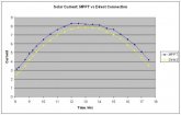
Here you go. Measured comparison 9 years ago on a 130W panel (8/4/2011, Santa Barbara, Ca). I used a switch to connect panel either to charge controller or directly to lead acid battery. The battery had a constant load to keep battery voltage from rising (battery voltage range: 12.2 to 12.3V). It appears around noon time MPPT output degrades due to temperature? Ambient temps are around 22C.

MPPT: total amp hours = 63.8
direct: total amp hours = 58.6

MPPT gain = 8.8%

Unfortunately Dacus is giving out false information to hype his product. 10 year life span of capacitors in a MPPT controller??? WTF? My CC is still going strong after 14 years of constant use. Clearly, MPPT has a performance gain over a direct connection, even in summer.


MPPT vs Direction Connection.JPG
 
Here you go. Measured comparison 9 years ago on a 130W panel (8/4/2011, Santa Barbara, Ca). I used a switch to connect panel either to charge controller or directly to lead acid battery. The battery had a constant load to keep battery voltage from rising (battery voltage range: 12.2 to 12.3V). It appears around noon time MPPT output degrades due to temperature? Ambient temps are around 22C.

MPPT: total amp hours = 63.8
direct: total amp hours = 58.6

MPPT gain = 8.8%
View attachment 22699

Thank you, useful info. Would be interesting to see how the gap between MPPT and Direct grew or shrunk season to season (well its SB so calling them seasons is a bit of a stretch ;)--but will still be interesting to see the difference between the mildly hot season and the not-that-hot-but-also-not-really-cold-season)

Unfortunately Dacus is giving out false information to hype his product. 10 year life span of capacitors in a MPPT controller??? WTF? My CC is still going strong after 14 years of constant use. Clearly, MPPT has a performance gain over a direct connection, even in summer.

While I think there are blindspots in his argument, and I think he tends to get laser focused on one particular use-case or factor and not fully acknowledge or consider alternative use-cases/design goals, I definitely don't feel that he is acting in bad faith or trying to hype his product. He is a very disarming and straightforward guy, and strikes me as very honest, even when I disagree with him or feel he is overlooking something.
 
Back
Top