Srvprelude
New Member
- Joined
- Apr 21, 2021
- Messages
- 9
Hello, first off thanks in advance for the help I have spent weeks researching and waiting for renogy's response (they did respond but did not answer my actual question, I left more confused then when I first started, a friend pointed me to this website, greetings! I hope someone here can point me in the right direction)
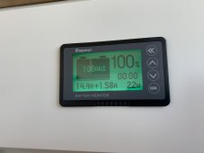
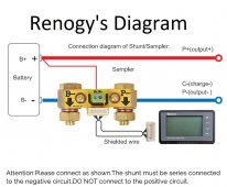
My problem: The renogy battery meter lcd screen will only show a discharge rate with down arrows on the screen, even in full sunlight with no load it never gets the up arrow indicating a charge. I did my best to understand renogy's instruction booklet, I found their cartoon drawing diagram the easiest but doesn't make sense to their verbiage in the booklet, I feel like something is not connected correctly?
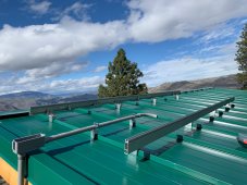
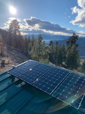
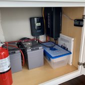
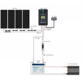
Setup: 4x100 watt renogy eclipse panels on the roof, feeding into a renogy rover 40a charge controller, that feeds 2x100AH renogy agm's in parallel, connected to a renogy 2000w pure sine wave inverter. Last weekend I added the renogy battery monitor screen/shunt in hopes of better accurate readings.
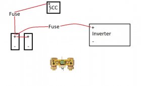
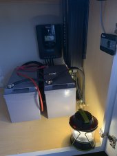
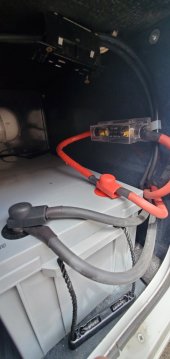
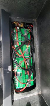
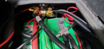
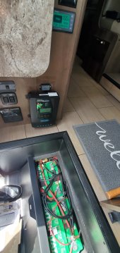
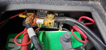
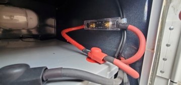
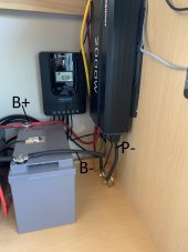
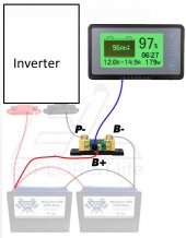
Currently the negative battery post is connected to the -B on the shunt bolt, on the outgoing side of the shunt the -P is connected to the inverter negative in lug, and then the little red B+ wire is connected to the 2nd battery positive post. With how it is wired, it only shows discharge rate. I have done all of the calibration etc, and I set up the max AH as 100 instead of 200 to protect from the 50% discharge rate. Please see photo of my temp install and wiring diagram showing how it is currently connected. What did I do wrong? Anybody run into this issue of showing discharge only, and never charging on the monitor screen?
(I'm heading back out there this weekend April 23rd with tools and hopefully a new plan to wire it correctly, its 160 miles from home)
Thanks in advance -Mike
My problem: The renogy battery meter lcd screen will only show a discharge rate with down arrows on the screen, even in full sunlight with no load it never gets the up arrow indicating a charge. I did my best to understand renogy's instruction booklet, I found their cartoon drawing diagram the easiest but doesn't make sense to their verbiage in the booklet, I feel like something is not connected correctly?
Setup: 4x100 watt renogy eclipse panels on the roof, feeding into a renogy rover 40a charge controller, that feeds 2x100AH renogy agm's in parallel, connected to a renogy 2000w pure sine wave inverter. Last weekend I added the renogy battery monitor screen/shunt in hopes of better accurate readings.
Currently the negative battery post is connected to the -B on the shunt bolt, on the outgoing side of the shunt the -P is connected to the inverter negative in lug, and then the little red B+ wire is connected to the 2nd battery positive post. With how it is wired, it only shows discharge rate. I have done all of the calibration etc, and I set up the max AH as 100 instead of 200 to protect from the 50% discharge rate. Please see photo of my temp install and wiring diagram showing how it is currently connected. What did I do wrong? Anybody run into this issue of showing discharge only, and never charging on the monitor screen?
(I'm heading back out there this weekend April 23rd with tools and hopefully a new plan to wire it correctly, its 160 miles from home)
Thanks in advance -Mike

")