I started out thinking I understood your diagram, but the more I look at it, the less confident I am that I understand it. I am going to try to spell it out, and please correct where I've got it wrong.
- Connect the shore power inlet (through surge protector) into inverter/charger AC-in
- Connect the master breaker to the inverter/charger AC-out
- Connect battery positive to inverter/charger DC-positive (via busbar?)
- Connect DC Distribution Panel battery/DC-positive (Part C in pictures) to inverter/charger DC-positive (via busbar?)
- Connect battery-negative to inverter/charger DC-negative (via busbar?)
- Connect DC Distribution Panel battery/DC-negative (Part D in pictures) to inverter/charger DC-negative (via busbar?)
All of the above is correct.
There's some other stuff I just dont understand.
- I dont understand what to do with inverter_charger.eg or chassis_bond. What is chassis bond?
Inverter_charger.eg refers to the equipment grounding lug on the inverter that is usually labeled ground.
Don't worry, grounding confuses everyone.
Just connect the inverter_charger ground lug to the negative busbar and connect the negative busbar to the frame of the travel trailer.
This link should explain more about grounding.
To get the paper, click on the orange button at the top of the screen. The subject of grounding is a complex, multifaceted subject, that is often treated as an after-thought but needs to be considered from the beginning of the design and build...

diysolarforum.com
My advice is not to get in the weeds with it for now.
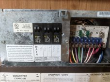
- Looking in my original pictures, what do I do with the CONV POS (converter positive). Just disconnect and wrap it up?
The easiest thing to do is just switch off the converter ac breaker.
The better thing to do is to remove the hot wire from the converter breaker and make it safe with a wire nut.
Do the same with the converter neutral wire.
The converter dc positive and negative can optionally be disconnected from the dc distribution panel.
Finally you could just remove the whole converter module and have an extra breaker position in case you want to wire in an extra ac circuit.
- Does this setup also use my battery bank to power the AC, CON(verter?), MIC(rowave), REF(ridgerator), and GFI outlets?
Yes
- If so, how could I change it so that the battery bank powers only the DC Panel stuff and the GFI outlets?
Just turn off all the breakers for the ac circuits you don't want to use.
Say you want to power the GFCI outlet and the fridge, just leave the master breaker on plus the branch circuit breakers for the fridge and the GFCI outlet.
- Just wire up the inverter/charger AC-out to the GFI breaker? If I did that, looks like I wouldnt be able to power the other stuff on shore power.
Yes all the ac circuits
Thanks so much for the time you took to write up a diagram, and apologies for my slowness.
On the contrary I'm impressed with how quickly you grasp this tricky subject.
One thing I forgot to mention is that inverter_chargers have an integrated automatic transfer switch so switching back and forth from shore power to battery power is seamless.
You shouldn't even see the lights flicker.