diy solar

diy solar

First draft of my LiFePO4 system - your input appreciated

CCinBR200

New Member
Joined
Feb 26, 2021
Messages
39
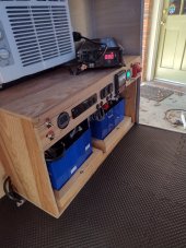
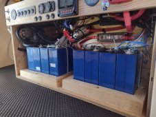
Here's my first attempt at designing my system. It's for a very cute 4'x8' camper called a Runaway. I bought (4) 280Ah LiFePO4 mystery cells on Aliexpress and thought they were defective (I was defective). Meanwhile, ordered (4) more 280Ah from Amy at Shenzhen Luyuan which are boating their way here. So now I have double the capacity I originally planned for. Since I assume they are of differing quality (e.g. internal resistance, age, etc), I am planning to run (2) independent packs, each with a BMS, with a switch. I would like to wire it so that I could have one pack charging while the other pack is used for loads but this is above my head. I'm open to suggestions about that if it doesn't make the setup too much more complicated.

I have the 120A Overkill BMS but thinking I might switch to the 150A BMS sold by Current Connected for the 2nd BMS. I see the owner posts here.

I've been trying to learn for a good while. I am open to any feedback that can make my system safer and more efficient / effective.

Wiring:

Batteries to Switch: 2/0 AWG
Switch to Busbar: 2/0 AWG
Busbar to Inverter: 2/0 AWG
Busbar to Charge Controller: 6 AWG
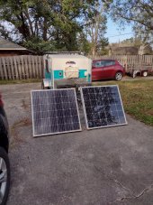
Controller to PV: 10AWG "Solar Panel Wiring"
Busbar to DC Fuse Block: 6 AWG

Thank you,

Carlo
 

Attachments

  • 12V 280Ah x 2 diagram.pdf
    24.3 KB · Views: 41
I forgot to mention: I know that my 400W of PV will have a hard time keeping up with use for this much Ah. It's a good enough arrangement because: 1) I can't really fit more on my little camper, 2) I make mostly 1 or 2 day trips. If I use the panels to charge the batteries ahead of a trip, I ma not use up all that is stored, even if I don't charge at all.
 
Last edited:
Is the 40A rating on the SCC the max input or the max output current? Assuming it's the max output then the 40A breaker between the SCC and the bus bar is too small. With an output of 40A you will have nuisance trips with the 40A breaker. Use a 50A instead.

You should have an appropriate fuse/breaker between the inverter and the bus bar. 250A would be about right.

Since you didn't post the specs for the panels or the SCC, have you verified that those two panels in parallel can safely be used with the SCC?
 
I recommend inline fuses between each array.
Thanks! Can you please explain this and/or draw it? I read through the "Overcurrent Protection Devices (OCPD) on Solar Arrays" Power Point from this forum and the author says no fuses are necessary for 2 panels in parallel.
 
Is the 40A rating on the SCC the max input or the max output current? Assuming it's the max output then the 40A breaker between the SCC and the bus bar is too small. With an output of 40A you will have nuisance trips with the 40A breaker. Use a 50A instead.
It's 40A max input. Does that still require a 50A breaker?

You should have an appropriate fuse/breaker between the inverter and the bus bar. 250A would be about right.
Thank you!
Since you didn't post the specs for the panels or the SCC, have you verified that those two panels in parallel can safely be used with the SCC?
Isc = 9.87A. I calculated Isc (9.87A) x 2 panels x 156% = 30.79 < 40A. Am I thinking right?

Thanks again!!
 
It's 40A max input. Does that still require a 50A breaker?
What is the max output current? That is what determines the breaker size needed between the SCC and bus bar.

Isc = 9.87A. I calculated Isc (9.87A) x 2 panels x 156% = 30.79 < 40A. Am I thinking right?
For making sure you don't exceed the 40A max input, the 156% factor is not needed so you are well within specs. But it's really important to make sure you don't exceed the max input voltage. What is the Voc of the panels and the max input voltage of the SCC?

You also need to account for these values going up in colder temperatures.
 
What is the max output current? That is what determines the breaker size needed between the SCC and bus bar.
It says "Rated Charge Current" = 40A; Rated Discharge Current = 40A. Is that the same. I can't find anything that says "Max output current". Attaching the manual. The model is 4210A.
For making sure you don't exceed the 40A max input, the 156% factor is not needed so you are well within specs. But it's really important to make sure you don't exceed the max input voltage. What is the Voc of the panels and the max input voltage of the SCC?
Voc = 24.335V. Max PV Open Circuit Voltage = 92V. @ 25 degrees C. I think I'm ok, right? Thanks for teaching me about these considerations. If there is a place for me to go and learn about the temperature considerations, let me know.

Thanks!
 

Attachments

  • Epever Tracer 4210A Manual.pdf
    1.1 MB · Views: 4
It says "Rated Charge Current" = 40A; Rated Discharge Current = 40A. Is that the same. I can't find anything that says "Max output current". Attaching the manual. The model is 4210A.
Since those are the only two currents listed in the manual and since they are both the same then I guess that means 40A max input and 40A max output (also known as max battery current - Ibat max).

So a 50A breaker would be much better than 40A as I stated earlier.

Voc = 24.335V. Max PV Open Circuit Voltage = 92V. @ 25 degrees C. I think I'm ok, right?
You're good. You could put 3 in series and still be fine.

If there is a place for me to go and learn about the temperature considerations, let me know.
If you look at the specs for your panels you should see something like "Temperature Coefficient Voc" and "Temperature Coefficient Isc". Based on those values you can see that Voc goes up as it gets colder and Isc goes down as it gets colder.

See:

for more of an explanation I posted recently.
 
See:
for more of an explanation I posted recently.
This was super-helpful!!
So a 50A breaker would be much better than 40A as I stated earlier.
Got it!
If you look at the specs for your panels you should see something like "Temperature Coefficient Voc" and "Temperature Coefficient Isc". Based on those values you can see that Voc goes up as it gets colder and Isc goes down as it gets colder.

My Voc is 24.335V and the temp coefficient is -.32% / degree C. I think the Voc is the same for 2 panels in parallel so I calculated Voc at 32F (26.28V) and at 0F / -18C (27.66V). So I think I'm safe to use a 30A Bussman DC Circuit Breaker like this between the panels and SCC, right, since the breaker israted at up to 42V?:


Since everything past the panels is at 12V, can I safely use breakers like these inline breakers? (I already have a supply of them):


Is the 300A fuse and 2/0 wire a proper match? i.e will the fuse blow before the wire burns up?

I had an MRBF fuse and holder directly attached to the positive lug on the pack when I had an AGM pack and thought I would stay with MRBF. I've been reading about the main fuses today and I think I will switch to T fuses right past the battery. Does this seem like a better / safer way to protect from catastrophic failure like a dead short as well as overloads?


Thanks!!
 
Last edited:
My Voc is 24.335V and the temp coefficient is -.32% / degree C. I think the Voc is the same for 2 panels in parallel so I calculated Voc at 32F (26.28V) and at 0F / -18C (27.66V). So I think I'm safe to use a 30A Bussman DC Circuit Breaker like this between the panels and SCC, right, since the breaker israted at up to 42V?:
I'm fairly sure that with only two panels in parallel you don't need a breaker between the panels and the SCC. If you add a 3rd then you need a combiner box with fuses. But otherwise your calculation seems correct. A breaker rated for 42V will handle those two panels in parallel. Keep in mind that if you decide to put the panels in series then a 42V breaker is insufficient.

Since everything past the panels is at 12V, can I safely use breakers like these inline breakers?
That statement may be confusing. Panels to the SCC can be up to Voc. If you really mean everything past the SCC then it is battery voltage (up to the bulk charge voltage setting which could be up to 14.6V).

I don't have any experience with those inline breakers so I'm not sure if they are appropriate or not. I used one of the Bussman breakers because it can safely be used as a disconnect as well.

Is the 300A fuse and 2/0 wire a proper match? i.e will the fuse blow before the wire burns up?
Yes, the 300A fuse can be safely used with the 2/0 wire assuming you are using high quality marine grade pure copper (optionally tinned) 105ºC wire. While 2/0 is suggested for up to 200A, it can be fused up to 350A. I like the Blue Sea chart at:


Then go down to the "Protect Your Boat With The Correct Size Wire And Fuse - Wire Size Chart" diagram.

I've been reading about the main fuses today and I think I will switch to T fuses right past the battery. Does this seem like a better / safer way to protect from catastrophic failure like a dead short as well as overloads?
I know a lot of people here recommend Class T fuses with LiFePO4 batteries. I currently have an ANL fuse but I will likely switch to a Class T.
 
Maddy,

Thank you for all of the help!!! I think I'm a smarter and safer installer since this thread started yesterday. You are cool human!

Carlo


I don't have any experience with those inline breakers so I'm not sure if they are appropriate or not. I used one of the Bussman breakers because it can safely be used as a disconnect as well.
Am I correct that my 1-2-Off switch is a master disconnect?
 
Am I correct that my 1-2-Off switch is a master disconnect?
It can disconnect the batteries from the rest of the system which will turn off the SCC and the inverter and the DC loads. So I'd call that a master disconnect.

However, before turning that main switch off you really need to make sure the breaker between the panels and SCC is turned off. You don't want to disconnect battery power from the SCC while there is PV coming in. Also make sure the inverter is turned off before turning the main battery switch off.

So while you might call it a master disconnect, other things must be disconnected before the master is turned off.

Turn everything on in reverse. Turn on the master first, then the inverter, then the panel breaker.
 
I'm fairly sure that with only two panels in parallel you don't need a breaker between the panels and the SCC.
I need to properly qualify this earlier statement.

While you don't need to fuse the panels when there are only two in parallel, you do want a breaker between the panels and the SCC that can act as a PV disconnect. So your plan to use that Bussman 42V 30A breaker would be a good choice to act as a disconnect. If you ever need to work on the panels you can turn off that PV breaker. If you ever need to disconnect power (the master or just to the SCC) then you first disconnect that PV breaker.
 
So I wrote to Samlex for advice about chassis grounding. FYI, this is a TINY camper and the existing electrical system (apart from the hitch wiring) is a 15A power strip that is powered by plugging into the campground power pedestal. Here are my questions and their answers:

1) Is it necessary to ground the SSW-2000-12V to the chassis?
  1. Yes
2) If so, should I also use 2/0 wire for this purpose?
  1. Check the RV code or best practices for this. I don’t have this information. It shouldn’t need to be this large.
3) Any other tips (e.g. match wire lengths?)
  1. You can use the sizing guides in our manual for the current carrying wires (positive /negative, line and neutral). Please refer to an RV technician or codes for electrical best practices.

Can anyone here weigh in on Question 2 especially about wire size? Also, any other input is appreciated.

Thanks!

Carlo
 
Hey! I got it finished and it works great! Dual 280Ah packs. This is a really great setup for a little 4'x8' camper! Thank you for all your support!!
 

Attachments

  • IMG_20220107_105043866_HDR.jpg
    IMG_20220107_105043866_HDR.jpg
    177.7 KB · Views: 16
  • IMG_20220107_105100291.jpg
    IMG_20220107_105100291.jpg
    250.1 KB · Views: 16
  • IMG_20220107_153714523_HDR.jpg
    IMG_20220107_153714523_HDR.jpg
    284 KB · Views: 16
Hey! I got it finished and it works great! Dual 280Ah packs. This is a really great setup for a little 4'x8' camper! Thank you for all your support!!
it looks great, wow, so much storage and power in a small space. great work
 
No fuse needed on two solar panels if the wires have ampacity to cary the max amperes of the panels. A switch is needed.
A fuse is needed for the inverter. All fuses should be sized to the ampacity of the wires being used, not the devices.
Provide some clamp support to the cells that the tops can not move.
You have done some neat work.
 
Back
Top