diy solar

diy solar

Help me with my solar schematic? ***I'm completely green***

Soiboughtavan

New Member
Joined
Jul 12, 2021
Messages
24
Wiring Diagram copy.jpg

Hello!

My name's Luke and my wife and I just bought ourselves a sprinter. Took the leap! I'm undertaking the electrical myself for this project, in hopes to have a better understanding of everything in the case of things going wrong while we're living in the tin can. Yup, we'll be full-time in it for as long as we can make it happen! I've been asking some electrician friends of mine for their opinion on this but they're not all that well-versed in off-grid systems. In advance, I can't begin to explain how grateful I am for communities like this one. Any advice is beyond appreciated. Let's get into it!

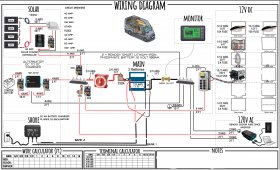
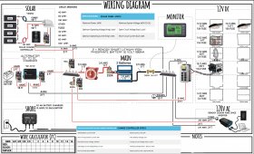
I took the Schematic from Faroutride.com and edited things to give me a better visual of the system I plan on building.

*Note* I'll likely use inline fuses instead of circuit breakers when I build. I'll also be adding a 12V usb dock.

I do already have some questions,

Should shore power connect to the bus bar as well?

Do I need a seperate spot on the bus bar for each connection?

How do I size the wire from the starter battery to the charger?

Will the NOCO Genius 10x2 give me sufficient enough shore power?

I'm considering installing a 2.5 US Gal Bosch Water Heater (Wattage - 1440) as well. Will I have enough storage with solar and the alternator?

Thanks for helping this GREENIE out! I'm thrilled to be a part of this community moving forward. Building this on my own is definitely unleashing the solar geek in me.
 

Attachments

  • Wiring Diagram.jpg
    Wiring Diagram.jpg
    719.2 KB · Views: 41
  • Wiring Diagram copy.jpg
    Wiring Diagram copy.jpg
    769.9 KB · Views: 12
  • Wiring Diagram copy.jpg
    Wiring Diagram copy.jpg
    786.6 KB · Views: 33
Last edited:
Firstly, if you have 4 panels wired in series, make sure your charge controller can handle over 100V if you ever have it in cold weather… VOC increases up to 25% in cold weather…

sizing chargers to bussbar wiring is usually upsize over the ampacity of the output. Meaning a 40A charger needs wiring to support 25% over 40A, then find a wiring ampacity calculator to get the right size wire. And fuse for the same load.
 
A few comments on things I notice off the top of my head:

The 40A breaker between the solar panels and the solar charge controller (SCC) is too large. With 4 panels in series you likely only need a 15A or 20A breaker there depending on the actual specs of the panels. You should update your diagram with the 4 main specs (besides watts) for the panels. Make sure this breaker is a proper PV breaker than can handle the high voltage from the 4 panels in series. Many DC breakers are only meant for lower voltage.

The 40A breaker between the SCC should be 50A. Since the output of the SCC is 40A, a 40A breaker will likely encounter regular nuisance trips.

You need to update your diagram with specs on the SCC. We know the 40A output but was is the max PV input voltage? You need to verify the Voc of 4 panels in series can't ever exceed that value. In cold temps that Voc can increase so you don't want the panels to be too close to the SCC's max.

While 8AWG from the panels to the SCC will work, it's probably overkill. With the panels in series the current will be low (another reason to show the specs). If it's only 10' long you likely can use 12AWG but possibly 10AWG, depending on the actual specs. The 8AWG from the SCC to the bus bars is good.

The shore power battery charger should be connected to the bus bars just like everything else.

The fuse and wire to the inverter is too small. A 2000W inverter at 12V can pull 167A. You probably want 2/0AWG, not 2AWG. And then the fuse should be 200A.
 
Screen Shot 2021-07-12 at 7.17.49 PM.png

This is already so helpful, thank you. I forgot that series and parallel swap voltage and amperage outputs.
Above is the specs for the solar controller. 100VDC would be sufficient?

Screen Shot 2021-07-12 at 7.17.15 PM.png

Above are the panels specs.
 
Check with NOCO but I don't think you can use both outputs on a pair of batteries connected in parallel. Although you could use one connection to keep the chassis (starter) battery charged.

If you go 2/0 to the inverter you can skip the second fuse (175a) for the 2' of wire to the inverter.

#4 to the DC-DC charger is a bit of overkill. #6 to and #8 from is fine.

The chassis ground on the inverter should go direct to the vehicle frame. #8 wire should be fine.
 
Last edited:
Those panels with a Voc of 22.3V in 4S will get to 99.5V at -10ºC (14ºF). Basically if you ever encounter temperatures much below freezing you risk destroying the charge controller. If your panels are mounted flat on the roof of the van and the sun is at a low angle when it's that cold, the risk may be minimal but I would look at getting a SCC that can handle a bit more than 100V if you want those panels in 4S.

Another option is to wire the panels as 2S2P. That would make the voltage plenty low enough for that SCC. The 40A SCC would still be able to handle the higher amps. And 2S2P is better for shading issues than 4S.

If you do put the panels in 2S2P then you can still use a 15A breaker since current is pretty low on those panels. But I would definitely choose 10AWG between the panels and SCC.
 
I don’t see a 40A breaker between the PV and the SCC, it is a 20A, and the wire says #10 which is fine for the little 8A series is capable of… I agree, the pictured breaker is inadequate, as it is only rated for 32V, and will exceed 100V but likely stay at around 72 or less under load… still over the 32V rating of that style breaker.
 
Those panels with a Voc of 22.3V in 4S will get to 99.5V at -10ºC (14ºF). Basically if you ever encounter temperatures much below freezing you risk destroying the charge controller. If your panels are mounted flat on the roof of the van and the sun is at a low angle when it's that cold, the risk may be minimal but I would look at getting a SCC that can handle a bit more than 100V if you want those panels in 4S.

Another option is to wire the panels as 2S2P. That would make the voltage plenty low enough for that SCC. The 40A SCC would still be able to handle the higher amps. And 2S2P is better for shading issues than 4S.

If you do put the panels in 2S2P then you can still use a 15A breaker since current is pretty low on those panels. But I would definitely choose 10AWG between the panels and SCC.
With the panels now wired in 2S2P the amperage output is only doubled correct (10.76)? I think wiring them in 2S2P is a brilliant idea, I never would have considered that or much of what you've suggested for that matter lol.

*** UPDATED THE SCHEMATIC ***
 
*** UPDATED THE SCHEMATIC ***
It might have been better to post the update as a new reply instead of editing the original post since now all of the earlier comments don't make much sense.

With the panels now wired in 2S2P the amperage output is only doubled correct (10.76)?
Yes, that's correct. The volts are doubled due to the 2S and the amps are doubled due to the 2P.

I agree, the pictured breaker is inadequate, as it is only rated for 32V, and will exceed 100V but likely stay at around 72 or less under load… still over the 32V rating of that style breaker.
To the OP - that reply reinforces my earlier comment about needing a proper PV breaker that can handle the high voltage from the panels. Midnight Solar makes some really good PV breakers that are designed for this use.
 
It might have been better to post the update as a new reply instead of editing the original post since now all of the earlier comments don't make much sense.


Yes, that's correct. The volts are doubled due to the 2S and the amps are doubled due to the 2P.


To the OP - that reply reinforces my earlier comment about needing a proper PV breaker that can handle the high voltage from the panels. Midnight Solar makes some really good PV breakers that are designed for this use.

I agree, I should have saved the previous ones.

Thank you for sharing your knowledge!
Check with NOCO but I don't think you can use both outputs on a pair of batteries connected in parallel. Although you could use one connection to keep the chassis (starter) battery charged.

If you go 2/0 to the inverter you can skip the second fuse (175a) for the 2' of wire to the inverter.

#4 to the DC-DC charger is a bit of overkill. #6 to and #8 from is fine.

The chassis ground on the inverter should go direct to the vehicle frame. #8 wire should be fine.

Thanks for bringing up the NOCO 10x2 concern. You were right to think that both outputs can't connect to batteries in parallel. I think I'll be swapping it for a NOCO 10x1
I don’t see a 40A breaker between the PV and the SCC, it is a 20A, and the wire says #10 which is fine for the little 8A series is capable of… I agree, the pictured breaker is inadequate, as it is only rated for 32V, and will exceed 100V but likely stay at around 72 or less under load… still over the 32V rating of that style breaker.

Thank you for your input!
 
Hello again, I'm curious.

Would a 250A Busbar be sufficient enough for this system or should I buck up and get the 600A?
 
Would a 250A Busbar be sufficient enough for this system or should I buck up and get the 600A?
Think of a bus bar as just another piece of wire that needs to be sized properly for the loads. Your highest single load is about 170A going to the inverter. Plus you may have 40A going to the DC fuse box. There could be 40A coming through from the SCC. Plus up to 40A from the DC-DC charger. Plus 10A from the shore power. If all of this was maxed out at once (not likely) your battery would be handling 300A.

Quick tangent: But you've chosen 2/0 cable to the battery which should only be used up to 200A. And you have a 250A fuse. 2/0 may be too small. Just having the inverter using the full 2000W while the SCC is pushing a full 40A gets you to 210A. 3/0 or 4/0 wire between the batteries and the bus bars might be better, especially if other things are using power at the same time as those two. And then the 250A fuse needs to be bigger to match.

Back to the bus bars. Even with your current setup, having a 250A bus bar and a 250A fuse is risky. If a huge surge comes through, the bus bar might fail before the fuse blows. Just like a wire, the bus bar must be able to handle more current than the fuse. The fuse must always be the weakest link. A 300A bus bar would be the minimum you should have for your setup. But if you upgrade to 3/0 or 4/0 between the batteries and bus bars, the bus bars should handle more like 350A or 400A to be worry free.
 
Hey Everyone,

I'm currently finalizing the schematic and would really appreciate any opinions that are out there!

I've started order things here and there but some items I've held back on ordering just to be sure I'm ordering the parts necessary to make this build safe and efficient.

The input here so far has been invaluable and I genuinely appreciate it.

Luke.

Wiring Diagram copy.jpg
 
One thing I just noticed is your choice of breaker between the panels and the SCC. With those panels in 2S2P, the Voc can reach 50V in colder temps. That kind of breaker is only rated for 48V (assuming that is a true Bussman breaker such as Blue Sea Systems). Knock offs could be lower. You should find a breaker that can safely support 60VDC or more. Midnite Solar sells PV specific breakers designed to handle 150V.

The 40A DC to DC charger only needs at 50A breaker, not 60A. I don't know if that 40A is the input from the starter battery or the output. Which ever side that 40A represents, you can replace the 60A breaker with 50A.

Shouldn't there be a negative wire from the starter battery to the DC to DC charger?

Why is the negative wire from the DC to DC charger sized at 4AWG when the positive wire is only 8AWG? If it is the output of the charger that is 40A, then both (pos and neg) wires can be 8AWG.

I would think the ground wire from the negative bus bar to the chassis should be 3/0 to match the 3/0 used for the battery.
 
Hey rmaddy, I was off-grid for a couple days. Sorry for the delayed response.

I've looked into Midnite Solar products, thanks for the recommendation. Do you think a 20 AMP/150 VDC Breaker will work out? What is the calculation for VOC maximums in cold temperatures?

You're correct, I should have a negative wire to the DC to DC. The fuse recommendations for the input to the DC to DC is 60 AMP and the output recommendation is 50 AMP. I suppose I should adhere to those recommendations hey?

Would there be any way to protect the Midnite Solar Breaker from moisture? It's like it won't see any but I was keen on having the majority of the components being marine grade. I live in the Pacific Northwest so rain is a GUARANTEE.

Thanks again for your input!
Wiring Diagram copy.jpg
 
I've looked into Midnite Solar products, thanks for the recommendation. Do you think a 20 AMP/150 VDC Breaker will work out? What is the calculation for VOC maximums in cold temperatures?
You originally had a 15A breaker so the 15A/150VDC breaker would work. But 20A is fine too since 10AWG wire can easily handle more than 20A.

Do make careful note that the MNEPV breaker is polarized. It's critical to get it wired correctly or it can actually be dangerous if you try to turn it off under load. One end (I think it's the bottom) of the breaker will be clearly marked as ++. The wire from the panels goes to the ++ end of the breaker. The wire from the other end of the breaker goes to the SCC.

Look at your panel specs and find a value for "Temperature Coefficient Voc". It will be something like -0.3 %/ºC. The actual number for your panels will be different but it will be a negative number less than 1. Then it's simple math. The Voc listed for your panel is the STC at 25ºC. If you want to know the Voc at -10ºC, for example, then you have -10ºC - 25ºC = -35ºC. Then -35ºC * -0.3 %/ºC (use your panel's actual value) = 10.5%. Your panel's Voc in 2S is 44.6V. So 10.5% of 44.6V is 4.7V. Finally 44.6V + 4.7V = 49.3V. So your panels can be up to 49.3V at -10ºC. Plug in the actual coldest temperature you may ever encounter and the actual value for your panel's Temperature Coefficient Voc and you can see the maximum Voc you could encounter.

Actual formula = Panel Voc * ((Desired Temp ºC - 25) * Temperature Coefficient Voc / 100 + 1)

Would there be any way to protect the Midnite Solar Breaker from moisture? It's like it won't see any but I was keen on having the majority of the components being marine grade. I live in the Pacific Northwest so rain is a GUARANTEE.
The breaker for you panel disconnect will be inside the trailer close to the SCC. You should use something like MidNite Solar's "Baby Box" enclosure for the MNEPV breaker. It has a DIN rail inside to mount the breaker. Since you will mount it inside with the SCC, rain shouldn't be a problem (or you have other big problems).
 
Last edited:
Good Morning!

Awesome information. I put an order in yesterday for everything I need to move forward with the solar/electrical build. I'll be sure to post some images of the finish product!

Subfloor going in the van today and roughing in electrical tomorrow(y)

Have a good weekend!
 
Hello again!

I'm having some difficulty finding decent 3/0 and 2/0 AWG wire. Any recommendations?
 
Back
Top