chrisski
Solar Boondocker
- Joined
- Aug 14, 2020
- Messages
- 5,279
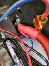
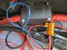
Turns out if you want to add a resistor to precharge your caps in your system, much easier when it is first installed.
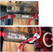
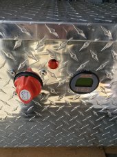
In my install, Turns out the Perko switch
won't able to be wired where I want it because of my installation
Because of the stud patten on the back of the Perko
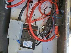
once secured would cause the wire going to the rest of the system to go up without a way to route to the busbar underneath it without totally redoing the powerboard. Not an easy task. I now will use thisBlue Sea Switch which is similar:
 with a bolt pattern like this:
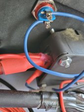
Just unsure what the alternator field disconnect does if wires are not hooked.
In my install, Turns out the Perko switch
won't able to be wired where I want it because of my installation
Because of the stud patten on the back of the Perko
once secured would cause the wire going to the rest of the system to go up without a way to route to the busbar underneath it without totally redoing the powerboard. Not an easy task. I now will use thisBlue Sea Switch which is similar:
with a bolt pattern like this: Just unsure what the alternator field disconnect does if wires are not hooked.