diy solar

diy solar

Van Conversion Wiring Diagram, Please Review

The core of the system should all be close enough together that voltage drop is not an issue.
I oversized the branch circuits to the maximum size and fused for the wire.
EZPZ.
If you want we can tweak the branch circuits.
Or I can teach you how to size your own
I thought people generally use 10 awg from the panels to the SCC, why does your diagram use 6awg?
 
I thought people generally use 10 awg from the panels to the SCC, why does your diagram use 6awg?
10 awg is only good for about 30 amps.
10 awg is used on the pv side of the scc but not necessarily on the system side.
I used 6 awg and 100 amp fuses to consolidate the bill of materials.

In the second drawing I used 2x 10 awg.
 
The panels are in series and their Imp is 9.8A and the Isc is 10.2A. Doesn't that mean at max power in series I can only expect to see 9.8A? why am I worried about 30A. Why do I need 2x 10awg, why not just 1x? Dude I feel confused and overcomplicated
 
The panels are in series and their Imp is 9.8A and the Isc is 10.2A. Doesn't that mean at max power in series I can only expect to see 9.8A? why am I worried about 30A. Why do I need 2x 10awg, why not just 1x? Dude I feel confused and overcomplicated

The solar charge controller has 2 sides, pv input and system output.
A single string of panels does not require a fuse.
The system side amperage could be up to ~50 amps.
The smallest fuse we could use on the system side is 60 amps.
50 amps / .8 fuse headroom = 62.5 amps
So we round it down to 60 amps.
But because I used 6 awg wire we can use a 100 amp fuse which has lower resistance.

On the second drawing I used 2 * 10 awg each with a 30 amp fuse.
30 amps is the max ampacity for a branch circuit on a fuse block.
 
The biggest difference between the drawings is the first one has busbars as the top level and the second drawing uses the fuse_block as the top level.
 
Oh I understand...
The pv side is almost always 10 awg for simple systems.
When we need to go above 10 awg then we usually use a combiner box between the panels and the scc.

The system side is what I am speccing the wires and fuses for.
The pv side is going to be 1 * 10 awg.
 
I'm lost. Please understand, I've never done any of this before. I don't even really know how to use a shunt like is being recommended. The battery protect is new and I just watched a video to see what a MRBF fuse is. I think I can understand your coded drawing. So where are we exactly? You're recommending using the 2nd drawing with 1X10awg on the PV side instead of 2X
 
I'm lost. Please understand, I've never done any of this before. I don't even really know how to use a shunt like is being recommended. The battery protect is new and I just watched a video to see what a MRBF fuse is. I think I can understand your coded drawing. So where are we exactly?
Question is to vague to answer.
You're recommending using the 2nd drawing with 1X10awg on the PV side instead of 2X
The first setup is good if you ever plan to have an inverter.
The second setup is cheaper and should serve you fine except it doesn't have a battery protect.
You loads are low enough current that its not that critical.
Its your choice but if you want me to decide I pick the second drawing just because its cheaper and smaller.

I impressed with your ability to assimilate all this new information.
Take a deep breath and splash cold water on your face, it always helps me.
Oh and coffee.
Haha I'm doing my best. I like the idea of being able to add an inverter. If I put the shunt in, what will I use to take readings? You agree on the 10awg for the pv side?
 
Haha I'm doing my best. I like the idea of being able to add an inverter. If I put the shunt in, what will I use to take readings?
I like this one
You use your smartphone as the interface.
You agree on the 10awg for the pv side?
Use 1 * 10 awg for the pv side.
Your panels will already come with 10 awg wire and mc4 connectors.
You will just need to make extensions with mc4 on the panel side and ferrules on the pv side.
Ok cool, the busbars drawing is the way forward.
 
New hopefully definitive version
Code:
legend {
    {} { functional block }
    nnn|NNN| { fused busbar position where nnn is wire size in awg and NNN is the fuse rating in amps }
    nnn|UUU| { un-fused busbar position where nnn is wire size in awg }
    <-> { bi-directional current flow }
    -> { uni-directional current flow }
    <- { uni-directional current flow }
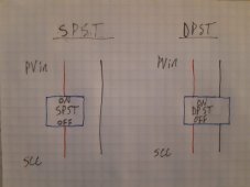
    dpst { double pole single through switch }
    @ { back reference }
}
dc_domain {
    busbars {
        positive {
            004|UUU|<->150A_breaker<->battery
            006|100|<-scc<-dpst<-panels(10awg)
            006|100|->battery_protect->fuse_block.feeders
        }
        negative {
            004|UUU|<->shunt<->battery
            006|UUU|->scc->dpst->panels(10awg)
            006|UUU|<-fuse_block.feeders
            016|UUU|<->chassis_bond
        }
    }
    fuse_block {
        feeders {
            positive@
            negative@
        }
        branches {
            positive {
                010|030|->fan
                010|030|->fridge
                010|030|->combo socket
                010|030|->combo socket
                016|001|->shunt_positive
            }
            negative {
                010|UUU|<-fan
                010|UUU|<-fridge
                010|UUU|<-combo_socket
                010|UUU|<-combo_socket
                016|UUU|<-battery_protect_ground
            }
        }
    }
}
 
Why is current flow on the battery bi directional if they are separated as + and - poles? Everywhere else is uni directional? Is this because the shunt and the breaker function of both incoming and outgoing current? On this same note, this means a current over 150A will trip that breaker. The SOK 206ah has a max continuous discharge current of 100A and a peak discharge current of 200A for 3 sec. If somehow I used something that draws over 150A from the battery it will trip that breaker right? Is this an unfounded concern because it's unlikely I would ever draw over 150A with a device or is it smart to size the breaker to 200A.

Also on the shunt, I was under the impression the smartsolar mppt would provide me all of the information about the battery I needed. What other info is the smartshunt going to provide that you find pertinent?
006|100|<-scc<-dpst<-panels(10awg)

006|100|->battery_protect->fuse_block.feeders

You are recommending the MRBF fuse for these 100A fuses right? Why are they sized for 100A?
016|001|->shunt_positive
Why is this only 1A fuse?

branches { positive { 010|030|->fan 010|030|->fridge 010|030|->combo socket 010|030|->combo socket 016|001|->shunt_positive
How are you determining 30A fuses here?
You will just need to make extensions with mc4 on the panel side and ferrules on the pv side.
You're recommending ferrules on the pv input side right? Is this just to make a nice clean connection into the mppt? Are they necessary or just aesthetically pleasing to you?
 
Why is current flow on the battery bi directional if they are separated as + and - poles? Everywhere else is uni directional? Is this because the shunt and the breaker function of both incoming and outgoing current?
The battery can be charged or discharged.
When its being charged the current goes backwards through the battery.
On this same note, this means a current over 150A will trip that breaker.
Yes.
Over-current devices have a trip curve.
One axis is current the other axis is time.

The SOK 206ah has a max continuous discharge current of 100A and a peak discharge current of 200A for 3 sec. If somehow I used something that draws over 150A from the battery it will trip that breaker right?
Yes but not right away.
Without actually looking at the trip curve I would guess 150% of rating for 60 seconds would trip the breaker.
A dead short will trip it in milli-seconds.
Is this an unfounded concern because it's unlikely I would ever draw over 150A with a device or is it smart to size the breaker to 200A.
If you want a 200 amp breaker then you need 2 awg wire.
Also on the shunt, I was under the impression the smartsolar mppt would provide me all of the information about the battery I needed.
Nope not even in the same ballpark as a shunt.
What other info is the smartshunt going to provide that you find pertinent?
State of charge.
The solar charge controller can't do that.
You are recommending the MRBF fuse for these 100A fuses right? Why are they sized for 100A?
Because the wire is 6 awg.
We size the fuse to the wire.
Actually for the battery protect circuit make that an 80 amp fuse.
Why is this only 1A fuse?
Because the current draw of the shunt will be 1 or 2 milli-amps and that is the smallest fuse that we can fit in the fuse_block
How are you determining 30A fuses here?
Because the wire is 10 awg and we fuse for the wire.
You're recommending ferrules on the pv input side right?
Yes.
Is this just to make a nice clean connection into the mppt?
Fine stranded wire without ferrules has a nasty habit of shorting to the neighbor terminal.
It also has a nasty habit of squirming in the terminals cause the terminal to become loose.
Loose connections can cause fires.
Are they necessary or just aesthetically pleasing to you?
Not strictly necessary but I strongly encourage them.

Did you explore my links to the mrbf stuff at waytek?
 
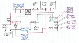
@smoothJoey Visual Diagram of your Ladder Drawing, how does it look?
wiring diagram 2.jpg
  • On the positive coming out of the smartshunt to the 1A fuse on the fuse box, will I be running this wire from "VBatt +" output (green area) on the shunt?
  • On the BatteryProtect, just curious on why I'm running it to the fuse box, isn't the negative bus bar a more direct path to ground? Does it matter?
  • We talked earlier about putting a master switch on the battery circuit, does the 150A breaker serve as this master switch?
  • I know you fused for wire size. The 12V fridge has a 15A internal fuse. By fusing it at the fuse box, basically this means if overcurrent occurs it will blow the fuse at the fuse box and not the fuse in the fridge, making for easy fuse replacement correct? Doesn't this mean I need to use a 15A fuse instead? (fusing for the appliance, not wire size)
  • On the same note, the manufacturer recommends a 10A fuse for the MaxxAir roof fan. Won't I want the fuse to blow just a bit above the appliance's max operating current instead of 20+A over with a 30A fuse?
  • You're recommending buying my bus bars, MRBFs, 150A breaker, and my fuse block from waytek correct? Or can I get the breaker and the fuse block from amazon? Also, where's the cheapest 100% copper wire and quality rings terminals? I want quality in my components, but for the best price of course!
 
Last edited:
Back
Top