diy solar

diy solar

How critical are identical lengths on parallel wired batteries?

vtoddball

New Member
Joined
Jun 6, 2022
Messages
7
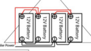
I've been digging through the forum and I'm seeing multiple posts about how batteries wired in parallel should have identical length wires between them. I understand the explanation of why, but I'm not seeing is a quantifiable "this is how bad it is" or "this is what degredation to expect." I built my install before I read about how critical this was so I have 4 - 200Ah, 12V batteries in parallel with a slightly longer wire right in the middle. Does anyone have a general idea how bad this is on a scale of 1-10? :LOL: I've included an image below. If I didn't already have a 12V Inverter I'd just swap it to two 24V in series.

battery1.jpg
 
Unequal cable lengths result in variable resistances. Longer cables have more resistance.

When you wire batteries with different resistances, they will share different portions of the load rather than share them equally. Thus if your bank is capable of 400A of discharge, you will not be able to run that high of a discharge. Your "center" batteries will experience lower current than the "outer" batteries, so your actual limit might a something closer to 360-380A since the outer ones will hit 100A before the inners.

In your case, the short cables joining the adjacent batteries should be as long as the longer cables joining the uppers to the lowers. The batteries on the left at which the main terminals are connected to the.

Your "end" batteries that connect the main (+) and (-) terminals will be subjected to higher currents than the right batteries. This is the norm when connecting 4 batteries in parallel. Your longer "center" cables will make it worse.

The main (+) and (-) wires do NOT need to be the same length.

How bad it is depends on the disparity. If all batteries are operating within specifications, they should meet rated cycle life; however, those that are seeing more current will likely have a shorter cycle life than those that see a lower current. Does this matter to you? Probably not unless you plan to place a high drain in this system.
 
Unequal cable lengths result in variable resistances. Longer cables have more resistance.
When it comes to the “posts” or “bus bars” wiring method for parallel batteries it is clear to me for the need of equal wire lengths so each battery has the same wire resistance.

But when I look at a “diagonal” wiring method it’s unclear to me what the effects are. In the OP’s case does the longer “center” wires really cause an imbalance?

Yes. The Wiring Unlimited 4 battery parallel "diagonal" results in imbalance along the lines of:

22A
18A
18A
22A

The longer "center" cables will make that worse.
 
It is important and Sunshine Ego covered it generally. By running Series to Parallel that get's a tad more "buggy".
Every connection, lug, terminal, SHUNT and Fuses ADD resistance and it is cumulative across the whole circuit.
With Lead Acid "Brute Force Tech" this kind of get's lost in the wash unless it is major ! With anything Lithium Based which are Millivolt & Milliohm sensitive, that is where even the piled up minutia can become an issue which presents problems differently.

This can be observed if you have exactly identical battery packs with the same SmartBMS', one will see slight differences between them, even if the cells are Perfectly Matched & Bached with the exact same IR's.

As for "Same" well precision to the Millimeter is assumed by many, there is a bit of give shall we say, an inch (2cm) or two (4cm) difference is "not" a big deal.
 
Yes. The Wiring Unlimited 4 battery parallel "diagonal" results in imbalance along the lines of:

22A
18A
18A
22A

The longer "center" cables will make that worse.
I don't see that. It's all based on total wire length through each battery, correct?

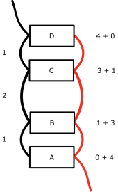
Here's a diagram I made modeled after the OP's setup.

diagonal.png

If the opposing negative and positive wires are the same length (the numbers down the left side) then the total wire length (positive and negative) to each battery is exactly the same (shown on down the right side). All 4 batteries have a total wire length of 4 so therefore they should all have the same resistance and therefore all contribute the same amount of current.

This seems to hold as long as the two wires between batteries A + B are the same, the two between B + C are the same, and the two between C + D are the same. Those three pairs do not need to be same as each other. (These are completely opposite requirements for the "posts" and "bus bars" setups.)

Am I correct here (only for this kind of "diagonal" wiring setup) or am I missing something?
 
the OP’s case does the longer “center” wires really cause an imbalance?
Yes. And No. Mostly no. Well other than they are not balanced by any means.
Yes. The Wiring Unlimited 4 battery parallel "diagonal" results in imbalance along the lines of:

22A
18A
18A
22A
Diagonal measures close to the same for me. I’d imagine the OP’s batteries would be like that
Am I correct here (only for this kind of "diagonal" wiring setup) or am I missing something?
You’re missing something. Those are not cabled in a balanced manner. These are:D7442CDB-CDFC-4D61-92CF-EBC3CDADD1C3.png
 
Last edited:
You’re missing something. Those are not cabled in a balanced manner. These are:
Your diagram is 2S2P, not 4P like mine so I don't see how it applies.

Edit: Your updated diagram is now 4P but it is "halfway", not "diagonal".
 
Last edited:
The diagram is 4P
You updated the diagram since my reply. It was a 2S2P diagram. Now it's a 4P diagram. But the updated diagram isn't using the "diagonal" wiring method. It's using the "halfway" wiring method. My comments are strictly about the "diagonal" method only (which is what the OP is using).

No. Those are 4P, but it's 2P(2P)
Yeah, 12VoltInstalls updated their post after my comment.

So my question still stands. Based on my earlier post with my "diagonal" diagram, is it or is it not actually balanced? If not, please explain why not. Thanks.
 
I have always seen this same advice on keeping all cables the same length in a parallel situation and have built my banks using that method so I am not arguing that it is a best practice.

That said, I have a theoretical question regarding this.

I believe that this whole discussion is based on the principal of Ohm's law (V = I x r). With that, if we have more resistance for a given current, then the voltage in the battery that has the highest resistance pathway will have the lowest voltage. Inversely, with the same voltage, the battery with the greatest resistance in its path will receive the least number of amps.

So, during bulk, the lowest resistance path will surge ahead and receive more amps of total current than the lowest and will fill faster. As the batteries get closer to full, their internal resistance will increase and they will start to self-limit so that the lagging batteries should start to catch up. Yes? / No?

Wouldn't this mean that if there is some absorption time, the lagging batteries should fully catch back up with their faster charging siblings? Isn't that basically what we do with top balancing cells? As the current diminishes, the voltage difference goes back into balance.
 
So my question still stands. Based on my earlier post with my "diagonal" diagram, is it or is it not actually balanced? If not, please explain why not. Thanks.
Very good question and I am also interested in the response.
 
No your diagram is not balanced. I am forced to agree with 12voltinstalls. His diagram is like number 4 in this aragements. http://www.smartgauge.co.uk/batt_con.html
Numbering OP battery as right to left top down. (1) (2) (3) (4). Connect (2+) onto (4+). Connect positive switch to (2+). Connect (1-) onto (3-). Connect system negative onto (3-). The shorter interconnections can stay as they are. Each shorter positive cable must be the same length. Each shorter negative cable must be the same length. Negative not need be same as positive. But it help. .Now we need to talk about fuses.
 
I am forced to agree with 12voltinstalls. His diagram is like number 4 in this aragements.
Yes, they are correct about that specific "halfway" wiring arrangement. No one is questioning that.

But the OP has a diagonal wiring arrangement. My question is specific to the diagonal wiring arrangement.

Some people have stated that the diagonal wiring arrangement won't be balanced but my own analysis (within the stated constraints) indicates that it is in fact balanced. The question is to confirm whether I am correct or not (and why).
 
Yeah, 12VoltInstalls updated their post after my comment.
FWIW I’m he. Sometimes that’s he he he :) but he. Not an it or a mere chromosome expression.
I selected the wrong image and I deleted immediately. Sorry about that. You were quick!
Based on my earlier post with my "diagonal" diagram, is it or is it not actually balanced? If not, please explain why not. Thanks.
Your posted diagram is indeed parallel, but it is not diagonal. It’s a linear string.
Actually the pic I posted is not empirically ‘diagonal’ either but is referenced as diagonal. It would look diagonal if the battery orientation was alternating.

Your diagram is not balanced. The one I posted seems to measure out balanced and it is how I have mine configured.

Plus I used 2/0. Or maybe 1/0 now that I think about it. The 2P cables I have are 2/0, and 2/0 to inverter.

Actually I have two banks of four 12V, 4P2P, because it becomes cable-crazy to balance eight batteries
 
Last edited:
It selected the wrong image and I deleted immediately. Sorry about that.
No problem.

Your posted diagram is indeed parallel, but it is not diagonal. It’s a linear string.
My diagram is "diagonal". Not sure what you mean by "linear". Look at the link Zil posted in post #15 and see its diagram #2 (perhaps your "linear" reference is diagram #1 at that link). Look at the "diagonal" diagram in chapter 3 of the "Wiring Unlimited" book from Victron. Both of those "diagonal" diagrams match what I posted.

Your diagram is not balanced. The one I posted seems to measure out balanced and it is how I have mine configured.
Once again, your diagram is the "halfway" wiring approach and is not relevant to my specific question about the "diagonal" wiring approach.

And please explain why my diagram is not balanced. We are trying to understand the why. Simply being told that it is not balanced doesn't answer the question. Thanks.
 
their internal resistance will increase and they will start to self-limit so that the lagging batteries should start to catch up. Yes? / No?
Sortof. But not really because:
if there is some absorption time,
A 12V lead acid battery is never actually full unless equalizing at 15.6V or so. Believe it or not. So absorption isn’t bumping against a ceiling if 14.4 exists. Or 13.8. The lead acid battery needs 10-15% above cell voltage to actually be charging so to a large extent the battery with the higher voltage just sits there and takes it, still reduced current capacity exists at “the next” battery, and everything starts to ‘balance’ but it could take a week to balance if you weren’t using anything.
Wouldn't this mean that if there is some absorption time, the lagging batteries should fully catch back up
The math and empirical science says that will happen but in practice? In the real world? Not really. But eventually yes, but after what stress to the battery that hangs at lower voltages?

Balance the cables, bulk in the mid 14s, and float 13.8 is the best outcome. Batteries aren’t a machine: we just inflict daily damage in the least destructive manner possible to create a useful lifespan we can live with. That’s not science, but it’s how I’ve gotten surprisingly long life out of cheap batteries for… 25? years?
 
My diagram is "diagonal". Not sure what you mean by "linear"
Oh! I misunderstood.
Diagonal in load terminals, but not in battery cable resistance or equality of cable length.
Once again, your diagram is the "halfway" wiring approach and is not relevant to my specific question about the "diagonal" wiring approach.
Now that I understand diagonal in load:
And please explain why my diagram is not balanced. We are trying to understand the why
Without doing the math (that I’d need to reference a few minutes to check myself cuz I ain’t no EE genius) from my observations of my own (and I knew it was wrong) stupidity of running a linear/diagonal string of six batteries all last summer - the middle two batteries could be nearly a full volt less after absorption, and under high load, the outer two batteries will drop lower than the middle two.

I think the amps with a meter would be slightly worse than the math would suggest.

In series the voltage and amps will hit the batteries the same (with your diagonal approach) because it has to conduct through the plates. In parallel, however, they are grabbing whatever they can while charging energy passes them by due to the linear cabling.
 
Back
Top