


You are using an out of date browser. It may not display this or other websites correctly.
You should upgrade or use an alternative browser.
You should upgrade or use an alternative browser.
DLG E-BOX 48100R, testing and tinkering.
- Thread starter mnd
- Start date
themizz
tinkering
For anyone having problems getting the serial cable to work. Here is the pin-out that should work, its based on a Pylontech cable, which these batteries and BMS seemed to be based on. The connection to the DB9 is based on a female, so if you wanted to solder on to a male DB9 you would invert the connections. (5 would goto 1 and 2 would goto 4, for example)
The latest version of the firmware ends in 1.1.3 if anyone is interested. Hyperterminal and TeraTerm seem to be good serial software to use.
I was having issues with using multiple batteries in parallel, the issue is 1 of the 4 was running an older version of the firmware. They must all be on the same version to get communication to work properly.
I'm being told that their battery view software is still coming out and they are testing it.

themizz
tinkering
Here is a link that support provided. Use at your own risk, but worked for me.
 drive.google.com
BMS update flies - Google Drive
drive.google.com
themizz
tinkering
Why did you upgrade? what does the upgrade solve?See .Bin attached within the .zip. Again, use at your own risk.
themizz
tinkering
I was having closed loop communications problems with my inverter. After checking the firmware version on each of my 4 batteries, one was on a different version. I had to upgrade all 4 to get them all on the same version for the comms to work properly.
Thank youSee .Bin attached within the .zip. Again, use at your own risk.
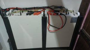
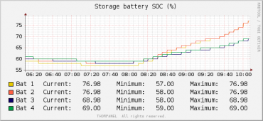
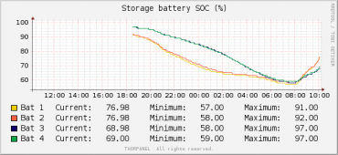
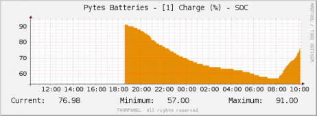
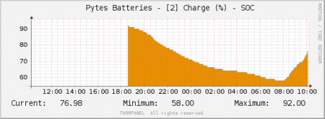
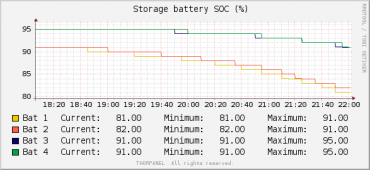
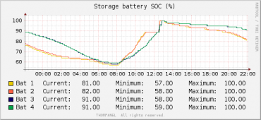
Guys i have 4 of this batteries and 2 growatts. I know see that i have unequall discharge.
All batteries are in parallel. First growatt is linked with the master (the first bat) and the second it`s linked with the last in the chain.
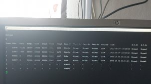
Power Volt Curr Tempr Tlow Thigh Vlow Vhigh Base.St Volt.St Curr.St Temp.St Coulomb Time B.V.St B.T.St
1 53828 8263 29000 26000 27000 3361 3368 Charge Normal Normal Normal 77% 2022-08-08 15:13:51 Normal Normal
2 53808 7216 29000 26000 27000 3360 3365 Charge Normal Normal Normal 76% 2022-08-08 15:13:50 Normal Normal
3 53845 3678 30000 26000 27000 3363 3367 Charge Normal Normal Normal 72% 2022-08-08 15:13:50 Normal Normal
4 53858 3500 29000 26000 27000 3363 3368 Charge Normal Normal Normal 72% 2022-08-08 15:13:50 Normal Normal
Any ideeeas on ballancing? All cables are the same length.
All batteries are in parallel. First growatt is linked with the master (the first bat) and the second it`s linked with the last in the chain.
Power Volt Curr Tempr Tlow Thigh Vlow Vhigh Base.St Volt.St Curr.St Temp.St Coulomb Time B.V.St B.T.St
1 53828 8263 29000 26000 27000 3361 3368 Charge Normal Normal Normal 77% 2022-08-08 15:13:51 Normal Normal
2 53808 7216 29000 26000 27000 3360 3365 Charge Normal Normal Normal 76% 2022-08-08 15:13:50 Normal Normal
3 53845 3678 30000 26000 27000 3363 3367 Charge Normal Normal Normal 72% 2022-08-08 15:13:50 Normal Normal
4 53858 3500 29000 26000 27000 3363 3368 Charge Normal Normal Normal 72% 2022-08-08 15:13:50 Normal Normal
Any ideeeas on ballancing? All cables are the same length.
themizz
tinkering
No busbar. Only cables same length and done as per manual. As per second image they go into idle if no high load!
I think it`s a bms thing. And also can someone tell me how to change the time on them it drives me crazy! Do you want to see graphs?
I think it`s a bms thing. And also can someone tell me how to change the time on them it drives me crazy! Do you want to see graphs?
Attachments
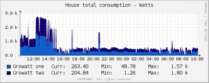
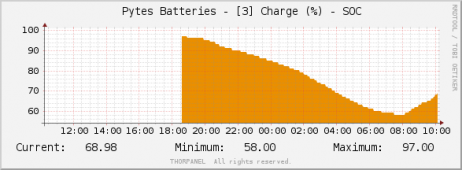
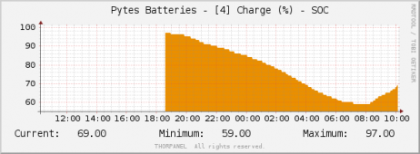
Nevermind here are some graphs! i have many more i only added a few!
Attachments
-
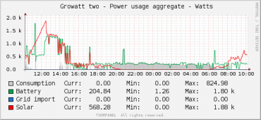 Power_usage_growat_2.png40.7 KB · Views: 15
 -
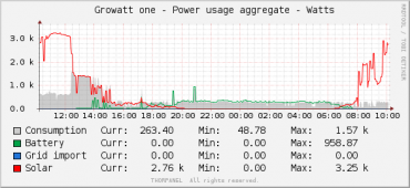 Power_usage_growat_1.png34.3 KB · Views: 13
 -
 Power_usage_agg.png31.9 KB · Views: 10
 -
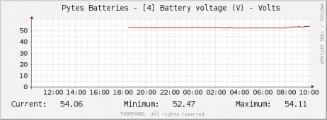 bat_4.png14.7 KB · Views: 10
 -
 bat_3.png14.4 KB · Views: 10
 -
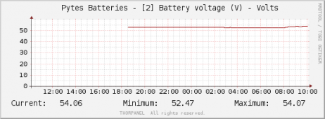 bat_2.png14.4 KB · Views: 9
 -
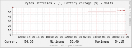 bat_1.png14.4 KB · Views: 11
 -
 AGG-SOC_2.png26 KB · Views: 10
 -
 AGG-SOC_1.png27.8 KB · Views: 13
Last edited:
You're gonna need to diagram what your setup is right now but I think you need to have one inverter take it's positive from battery 1 and negative from battery 4, and the other inverter, the exact opposite.No busbar. Only cables same length and done as per manual. As per second image they go into idle if no high load!
I think it`s a bms thing. And also can someone tell me how to change the time on them it drives me crazy! Do you want to see graphs?
I did exactly that today for the moment 2 bats are at 82% and 2 at 93%. Now the first invertor is positive from bat 1 and negative from bat 4. And the second invertor positive on bat 4 and negative on bat 1.You're gonna need to diagram what your setup is right now but I think you need to have one inverter take it's positive from battery 1 and negative from battery 4, and the other inverter, the exact opposite.
Power Volt Curr Tempr Tlow Thigh Vlow Vhigh Base.St Volt.St Curr.St Temp.St Coulomb Time B.V.St B.T.St
1 53017 -4591 30000 26000 27000 3310 3316 Dischg Normal Normal Normal 81% 2022-08-09 21:58:14 Normal Normal
2 53038 -4354 29000 26000 27000 3312 3317 Dischg Normal Normal Normal 82% 2022-08-09 21:58:13 Normal Normal
3 53020 -2170 30000 26000 27000 3311 3316 Dischg Normal Normal Normal 91% 2022-08-09 21:58:13 Normal Normal
4 53003 -2222 29000 25000 26000 3310 3316 Dischg Normal Normal Normal 91% 2022-08-09 21:58:13 Normal Normal
Look at the voltages on batteries don`t you think the charge is wrong? 53.017v 81% and 53.020 is 91%
Seems to be calculated from remaining mAH. on Bat 1 80468 mAH on Bat 3 is 91206 mAH. The pictures are after the wire change!
Attachments
Last edited:
Similar threads
- Replies
- 0
- Views
- 167
- Replies
- 1
- Views
- 310
- Replies
- 39
- Views
- 2K
- Replies
- 1
- Views
- 179