diy solar

diy solar

Heavy duty busbar advice (+600A)

da9el84

New Member
Joined
Apr 21, 2022
Messages
110
So, I'm building fairly big, 43kW panels, 3x12kW Deye SG04LP3 inverters and 3x48v@280Ah Mason DIY kits

For charging and discharging the batteries I am aiming for less than 0.5c on regular use, but I could have situations where a higher load is required and thus I need to run a little less than 200A from each battery(BMS max 200A), giving me around 600A.

So I need busbars that can handle a load like that.

For 3 inverters and 3 batteries, I need at least 6 connection points, cables from the battery come standard with 50mm2 lugs and I plan on running the same from the inverters.

Does this exist in the market? If so, can you point me to it, because I haven't been able to find it.

I saw something clever on a Seplos installation video and I was hoping to have something similar, just with its own enclosure as I not building a rack.
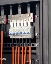
1660239331904.png

Preferably something that's purchasable within the EU.
 
Last edited:
I am going to answer a bunch of questions you did not ask.

Let's start with some math:

The three 12KW inverters can draw as much as (12000x3)/48 = 750A if fully loaded and the batteries are low. (Surge currents could be a lot higher). Consequently, the 3 batteries at 200A each are undersized for the inverter's capabilities.

Assuming you are OK with that, let's go ahead with an assumed 600A max current. (Even that is a huge amount of current to be herding around).

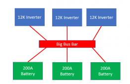
If all the batteries feed into the busbar and all of the inverters come off the busbar individually, then the busbar is the only place that has to handle all 600Amps.

1660331451645.png

Let's assume that any one of the inverters could have up to it's max current even if all 3 never do it at the same time. That means the Wire from the busbar to the inverter must carry 12000W/48V = 250A. Meanwhile, the wires to the battery must carry 200A.

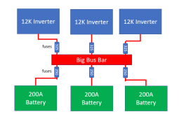
Now let's imagine a short circuit at one of the inverter inputs. In this case, the full 600A of battery current would attempt to flow through the wire. This means there must be a fuse or breaker at the busbar for each wire going to an inverter. The Fuse should be 1.25x the expected current so it should be 1.25 x 250A = 312.5A. You will need to round that up to 325 or 350A to get a fuse that works. Note that the wire should be large enough to handle the Fuse rating.

Now let's imagine a short right at the output of one of the batteries. In this case the short will drae the full 200A from the battery and 400A from the other two batteries. This means there needs to be a fuse at the busbar for each of the wires going to a battery even though the BMS will have overcurrent protection. The fuse should be 1.25x200= 250A. The wire should be large enough to handle the fuse current.

1660332603737.png

You might be able to get away with a busbar rated for 600A, but I would feel safer if the busbar could handle the combined fuse rating of all 3 input fuses: 3 x 250 = 750A.

I am not aware of an enclosed busbar of that size, but I have never tried to find one either.

Note: the busbar and wiring would be the same on the negative side but without the fuses. However, if you want a shunt on the negative side, it is going to require a > 600A shunt and the wiring between the shunt an negative busbar should be sized to handle 750A.
 
If you have any metal fabrication capabilities, it is easy to make the busbar to meet the amp requirements:

I have bought copper flat bar stock and made my own busbar.
Here is an example of what I search for on ebay, when I can't find a local supply:

Screen Shot 2022-08-12 at 18.41.42.png
 
Max DC Amps to or from my two Sol-Arks= 370A. I have 10 280aH batteries connected to 1/4" x 2.5" x 7' (capable of 1000A) tin plated copper bus bar. 3/0 x 6' cables from each inverter going to opposite ends of bus bars. 100A circuit breakers, 2 ga cables, 125A class T fuses. 10 JK BMS 200A rated, set to 100A max. Typical max current noted on any of the 10 batteries 37A. Usually runs 0-30A. You need a minimum of 6 batteries for redundancy, longer life, maintenance/repairs and one day without any pv input. I can do three days.
 
Last edited:
I am going to answer a bunch of questions you did not ask.

Let's start with some math:

The three 12KW inverters can draw as much as (12000x3)/48 = 750A if fully loaded and the batteries are low. (Surge currents could be a lot higher). Consequently, the 3 batteries at 200A each are undersized for the inverter's capabilities.

Assuming you are OK with that, let's go ahead with an assumed 600A max current. (Even that is a huge amount of current to be herding around).

If all the batteries feed into the busbar and all of the inverters come off the busbar individually, then the busbar is the only place that has to handle all 600Amps.

View attachment 106584

Let's assume that any one of the inverters could have up to it's max current even if all 3 never do it at the same time. That means the Wire from the busbar to the inverter must carry 12000W/48V = 250A. Meanwhile, the wires to the battery must carry 200A.

Now let's imagine a short circuit at one of the inverter inputs. In this case, the full 600A of battery current would attempt to flow through the wire. This means there must be a fuse or breaker at the busbar for each wire going to an inverter. The Fuse should be 1.25x the expected current so it should be 1.25 x 250A = 312.5A. You will need to round that up to 325 or 350A to get a fuse that works. Note that the wire should be large enough to handle the Fuse rating.

Now let's imagine a short right at the output of one of the batteries. In this case the short will drae the full 200A from the battery and 400A from the other two batteries. This means there needs to be a fuse at the busbar for each of the wires going to a battery even though the BMS will have overcurrent protection. The fuse should be 1.25x200= 250A. The wire should be large enough to handle the fuse current.

View attachment 106590

You might be able to get away with a busbar rated for 600A, but I would feel safer if the busbar could handle the combined fuse rating of all 3 input fuses: 3 x 250 = 750A.

I am not aware of an enclosed busbar of that size, but I have never tried to find one either.

Note: the busbar and wiring would be the same on the negative side but without the fuses. However, if you want a shunt on the negative side, it is going to require a > 600A shunt and the wiring between the shunt an negative busbar should be sized to handle 750A.

Thanks for that thorough answer and yes this is exactly how the system is planned out, however with max draw limited on the inverter side, as I don't plan on ever pulling or charging at full battery capacity (1C).

My BMS's are limited at 200A and the inverter itself is limited at 240A, hence the 600A max load pull.
 
Get the Victron Lynx, it is rated for 1000 Amps.

Check this video:

Thanks, it was actually my backup go to, it's just ridicously expensive(lynx distrubution costs +350 dollars here and I need 2 because it only has 4 connections each)
 
Last edited:
If you have any metal fabrication capabilities, it is easy to make the busbar to meet the amp requirements:

I have bought copper flat bar stock and made my own busbar.
Here is an example of what I search for on ebay, when I can't find a local supply:

View attachment 106612

I would have done this easily, my dad has a full metal workshop, but in Denmark this would never pass inspection(even though a busbar is exactly this) it has to have a CE rating and has to have an enclosure that requires tools to open.
 
Max DC Amps to or from my two Sol-Arks= 370A. I have 10 280aH batteries connected to 1/4" x 2.5" x 7' (capable of 1000A) tin plated copper bus bar. 3/0 x 6' cables from each inverter going to opposite ends of bus bars. 100A circuit breakers, 2 ga cables, 125A class T fuses. 10 BMS 150-250A rated, set to 80A max. Typical max current noted on any of the 10 batteries 40A. Usually runs 0-30A. You need a minimum of 6 batteries for redundancy, longer life, maintenance/repairs and one day without any pv input. I can do three days.

Yeah, I'd love to just do a simple tinplated copper busbar with standoffs, but regulations......

I don't need that much battery capacity, the grid in Denmark is the worlds most reliable powergrid. We can run the house for 1 normal day with this setup, but we rarely see more than a few hours of blackout each year.
The plan is to use the batteries to charge from grid in the winter and have logic built to monitor our fluctuating prices, so that we can tap power when it's cheap and then use it in the house when it's not.
Prices here each day can swing 100s of percentages.
 
I would have done this easily, my dad has a full metal workshop, but in Denmark this would never pass inspection(even though a busbar is exactly this) it has to have a CE rating and has to have an enclosure that requires tools to open.
enclosure could easily be 3d printed.

i know seplos sells a busbar system too, however, i think the victron solution will be faster and easier to get in denmark ( or a dutch webshop as you are in the eu, and so is victron)
 
enclosure could easily be 3d printed.

i know seplos sells a busbar system too, however, i think the victron solution will be faster and easier to get in denmark ( or a dutch webshop as you are in the eu, and so is victron)

I can't print an enclosure with a CE rating :p

Seplos only offers one that does 300A unfortunately.

I can do the Victron option, I'm just a little pissed that I need to pay +350USD x2 for a glorified tinplated copperbar.
 
I can't print an enclosure with a CE rating :p

Seplos only offers one that does 300A unfortunately.

I can do the Victron option, I'm just a little pissed that I need to pay +350USD x2 for a glorified tinplated copperbar.
if i were evil, i's simply print the CE mark in the plastic ;)

yeah , victron isnt cheap, dutchies ( like germans and the french ) do know the worth of a name in euro's ;)
 
I can't print an enclosure with a CE rating :p

Seplos only offers one that does 300A unfortunately.

I can do the Victron option, I'm just a little pissed that I need to pay +350USD x2 for a glorified tinplated copperbar.
They are ~ $175 each USD here in the US.

Outback has a Battery Combiner but it's going to more money than the Lynx.
 
They are ~ $175 each USD here in the US.

I've made a mistake I think, I've been searching for the wrong Lynx part. I was looking for the distributor, but I should have been looking at the Power In. It's the same price here :ROFLMAO:
 
Got things turned around after watching Explorist life on youtube yesterday :D Doh. Thanks for the help everyone, I'll probably just grab a couple of those
 
Back
Top