Solgato
New Member
- Joined
- Jul 15, 2020
- Messages
- 56
So I have an odd thing happening that I’m trying to get to the bottom of.
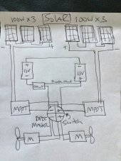
I have 2 12V LifePo4 batteries wired in Series for 24V with a Victron shunt and BMV-712.
The batteries are charged via dual Victron 75/15 MPPT charge controllers fed by 600W of panels.
All Victron devices are networked together.
I never fully discharge the batteries which power a Solar electric boat.
The chargers are set to float at 27V and Absorb at 29V.
The problem:
A few times now I have taken the boat out given it throttle only to see the voltage drop significantly in direct relation to throttle input. The motors then go into a protection mode since the voltage has dropped below 20V, a Limp Mode of sorts if you will. During that time the voltage from the solar system (60V) will provide some power to allow the motors to limp along.
In this situation it’s obvious the batteries are not giving power under load, but rather the solar panel voltage.
Testing once I get home, I find that while the batteries are still wired up/connected in Series with the solar chargers turned off, one battery measures 14V and the other -12.4 or so.
If I disconnect the negative terminal that is fed from the shunt of the battery that shows the reverse polarity battery, it measure +13V.
As soon as you hook it back up, it measures negative again.
The shunt and BMV in this scenario don’t function as it must not be getting/measuring 24V.
I forgot to but should have measured across the whole bank to see what it measures (the batteries are in separate hulls).
If I turn the solar chargers back on the Shunt and BMV work and everything appears okay Voltage-wise except that there is no current being reported as moving into or out of the bank as if the Shunt is only able to report voltage.
The best theory I can come up with is that perhaps one battery is disconnecting in between charge cycles due to low voltage, or perhaps during a charge cycle due to over charge, and that is somehow causing an imbalance between the batteries? Or they are drifting apart in capacity? But how would that explain the behavior?
I don’t know, I’m really stumped on this one.
The last time it happened I disconnected the batteries and charged them independently using a straight charger until they reached an equal state of charge and resting voltage. Seemed okay after that and was for a number of months, but maybe there is some other issue at play.
I guess the next step is to capacity check each battery.
Both were purchased new at the same time and are about a year and a half old, only used in this boat from day one which sits mostly in the yard until I take it out weekly. During the night there is a very small draw from the BMV and remote linear actuators controllers, and so everyday it goes through a minor charge cycle. I’m hoping now with Victrons ability to Data Log, I’ll be able to see exactly when this phenomena happens although I suspect it would show as a 0V and not negative if it happens at night because the BMV would turn off completely since it wouldn’t be getting 24V.
I know batteries can reverse polarity, but that doesn’t seem to be the issue since it measures correctly when disconnected. Instead it seems to be somehow related to the Series connection or perhaps the Shunt since it’s the battery closest to it.
I didn’t think I would need a Balancer with these with the way they get used, but I may have to install one.
Right now I’m drawing some power out of the 14V batt to get it closer to the other, then I’ll separately charge them again.
Maybe before that I’ll try to get a voltage reading across the whole bank without the charger on if the one battery is still doing its thing.
Anything else I should check while I’m trying to get to the bottom of this issue?
Thanks!