


You are using an out of date browser. It may not display this or other websites correctly.
You should upgrade or use an alternative browser.
You should upgrade or use an alternative browser.
Ac Coupled Inverter and Battery
- Thread starter Welshman
- Start date
newbostonconst
Solar Enthusiast
- Joined
- Sep 24, 2019
- Messages
- 1,005
Will need to know what you have....
Are you net metering? Do you want the inverters on the grid side of your hybrid inverter or the output side?
Are you net metering? Do you want the inverters on the grid side of your hybrid inverter or the output side?
OzSolar
Whatever you did, that's what you planned.
It's not a video but it does show the big picture and some of the finer points for SMA but they only have two AC connections, one for loads and one for the AC source (Grid OR Gen).

there is no hybrid inverter, that's why you do AC coupling....if it was a hybrid inverter, i could just add batteries to the hybrid.Will need to know what you have....
Are you net metering? Do you want the inverters on the grid side of your hybrid inverter or the output side?
To add battery storage to a string inverter, you do ac coupling
its not really what im looking for.....what i want is a video showing how to add ac coupling to an already fitted string inverter and panels . to add battery storage later down the line if needed. as it doesnt need MCS certification i was hoping to do it myselfIt's not a video but it does show the big picture and some of the finer points for SMA but they only have two AC connections, one for loads and one for the AC source (Grid OR Gen).
View attachment 115913
there 's no general way to do it, depend on the inverter you going to use.
With DEYE inverter you simply connect your grid inverter AC output or micro inverter AC output to the DEYE GEN input and check option "Micro Inv Input " in GEN PORT USE setting. A video won't show anything useful in this case.
With DEYE inverter you simply connect your grid inverter AC output or micro inverter AC output to the DEYE GEN input and check option "Micro Inv Input " in GEN PORT USE setting. A video won't show anything useful in this case.
newbostonconst
Solar Enthusiast
- Joined
- Sep 24, 2019
- Messages
- 1,005
If you just want to add more solar then just add it to your breaker box like your existing solar.there is no hybrid inverter, that's why you do AC coupling....if it was a hybrid inverter, i could just add batteries to the hybrid.
To add battery storage to a string inverter, you do ac coupling
AC coupling is mostly referenced when you have inverters/micro inverters attached on the output side of a hybrid inverter....when attached on the output side of the inverter the energy has no place to go if there is over production so the hybrid inverter changes the frequency of its output ac so the new/added inverter sees this and shuts down as not to fry other components.
Common inverters push the energy back into the grid as called net metering or the inverters has CT meters to tell if it is producing to much power or in off grid it targets a voltage level I believe.
Its not to add solar….its to add battery storage to an already existing system, without messing with the current set-up.If you just want to add more solar then just add it to your breaker box like your existing solar.
AC coupling is mostly referenced when you have inverters/micro inverters attached on the output side of a hybrid inverter....when attached on the output side of the inverter the energy has no place to go if there is over production so the hybrid inverter changes the frequency of its output ac so the new/added inverter sees this and shuts down as not to fry other components.
Common inverters push the energy back into the grid as called net metering or the inverters has CT meters to tell if it is producing to much power or in off grid it targets a voltage level I believe.
Advantages of AC-coupled high-voltage-battery over alternative solutions? - Sunny. SMA Corporate Blog
High voltage batteries only arrived in the market in the last 12 months. However their arrival has allowed a number...
Hedges
I See Electromagnetic Fields!
- Joined
- Mar 28, 2020
- Messages
- 21,061
A video, to show you how to do it?
A video might show connections happening at one point, but you couldn't see how wires go to grid and existing inverters.
The drawing posted above shows PV inverters connected to AC1 of Sunny Island, and grid connected to AC2.
Look up another drawing showing PV inverters connected to grid.
Cut wires between PV inverters and grid, insert Sunny Island, connect the wire ends to AC1 and AC2 as shown.
Finer points:
1) Determine if your existing GT PV inverters implement frequency-watts (a feature of UL-1741-SA or Rule-21, might require firmware update.)
2) In the U.S., Sunny Island is 120V but most GT PV inverters are 240V, so two Sunny Island are required
3) Limits on how much GT PV wattage can pass through to grid, and how much can be managed while grid is down. Review specs and manual of whatever battery inverter you plan to use.
There are other ways to make the connection, depending on your existing system configuration, how automatic you want this to be. I could just connect a pair of Sunny Island to existing breaker panel (AC2 input to one breaker, AC1 to a second breaker with interlock to main breaker) and use that for manual switchover.
Unless inverters and battery are large enough to power entire house, you will need to either manually disable excessive loads or wire the system to only back up smaller loads.
In case you get that wrong, it is useful to have a way to automatically shed most/all loads and keep only critical loads or just GT PV powered so batteries can recharge.
Grid Tie PV is trivial to design and implement, and almost any system just works. Battery Backup requires design and decisions.
A video isn't likely to document everything. Schematics and user manuals do, and posting your design for review would give an opportunity for problems to be caught.
newbostonconst
Solar Enthusiast
- Joined
- Sep 24, 2019
- Messages
- 1,005
Advantages of AC-coupled high-voltage-battery over alternative solutions? - Sunny. SMA Corporate Blog
High voltage batteries only arrived in the market in the last 12 months. However their arrival has allowed a number...
So they are making a hybrid inverter with less functionality but with a battery build in....WoW
What is the cost on that thing....Article is from 2017....surprised I am just seeing this thing.
OzSolar
Whatever you did, that's what you planned.
Somehow my keyboard sent a message. Can't delete it so I'll leave you with this which has nothing to do with this post which I regret responding to.
I must say I'm very impressed with the folks at 18650 Battery Store and Midnite Solar.
I must say I'm very impressed with the folks at 18650 Battery Store and Midnite Solar.
Last edited:
Hedges
I See Electromagnetic Fields!
- Joined
- Mar 28, 2020
- Messages
- 21,061
Advantages of AC-coupled high-voltage-battery over alternative solutions? - Sunny. SMA Corporate Blog
High voltage batteries only arrived in the market in the last 12 months. However their arrival has allowed a number...www.sma-sunny.com
So they are making a hybrid inverter with less functionality but with a battery build in....WoW
What is the cost on that thing....Article is from 2017....surprised I am just seeing this thing.
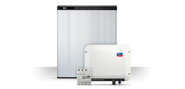
External battery.
The battery looks like LG RESU-H, which was listed as compatible with Sunny Boy Storage.
I think Sunny Boy storage is a Sunny Boy programmed for bidirectional operation with battery instead of PV.
The inverter in the picture looks like one of the European models.
SMA now has a 10kW 3-phase hybrid in Europe, with one input for battery and two for PV.
Sunny Boy Storage 6.0 kW is about $2500
The batteries were too high priced for my liking.
SMA just broke their U.S. website, doesn't have any documents except manual.
European site still has it, several brands supported:
Similar threads
- Replies
- 35
- Views
- 2K
- Replies
- 10
- Views
- 326