diy solar

diy solar

center tapping a serial battery string

Over and over I keep hearing that term split phase on this site.
Maybe its a solar thing.

Split phase often refers to a motor connection with or without capacitor for single phase motors...

The AC system for low voltage power distribution you refer too is properly called the Edison 3 wire system.
No one is ever confused by that no matter where you in the world, even if they do not use it....
Have you ever opened up a North American pole top transformer and looked at its wiring? If so you’d understand why any people call it split phase. Think of converting a 120v motor to a 240v motor. The same can be done with a pole top xfrmr, but in reverse, for twice the current capability at only 120v.

Not many people use this term in correctly as it’s AC only.

Also Edison was a DC guy, you’d want Westinghouse standards.
 
Have you ever opened up a North American pole top transformer and looked at its wiring?


Have you ever change an S&C fuse by the pale moon light lol
Call me out out on this if you can

I admit I’m probably splitting hairs here and have never frequented a forum full of Americans who speak electrical.
Split phase just sounds funny since it’s a single phase service with a centre tap and I never heard it call that before.
 

Attachments

  • 1A9243AC-7E00-425B-9C2F-B2C342CB5B4A.jpeg
    1A9243AC-7E00-425B-9C2F-B2C342CB5B4A.jpeg
    149.6 KB · Views: 11
Last edited:
When in doubt YouTube

I went looking for this and found that it’s not that uncommon to call it split phase


Generally I have only ever heard to differentiate a type of single phase motor from another.
Universal, repulsion, and the kind with a aux winding commonly referred to up here as split phase.
 
Last edited:
Folks,
So from a strict voltage standpoint, if I had two 12V batteries in parallel, the pos to neg connection is at 12V relative to ground.
If I had a small intermittent 12Vload, what are the dangers / downsides of feeding those loads from the battery bank center?
Certainly, if a large long-term load was feed this way the 0-12 volt battery would be out of balance relative to the 12V - 24V battery.
Would this imbalance eventually clear / stabilize during a series of charge discharge cycles? Or would it slowly get worse.
Thanks
Andy
Assuming your first sentence is two 12V batteries in SERIES, and the batteries are LiFePO4 with BMS.

I find it best to use 12V charge controllers for each series battery, and 24V inverter for the series pair.

Then it is fine to run 12V loads from individual batteries.

This obviously isn’t an option if you use all-in-one inverter/chargers.
 
No he brought up pole mount transformers “cans”.
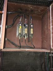
The fuses you see are typical of utility style fuses
Those ones are macgraw Edison fuses from some types me before the mid 80s
Not actual S&C brand

It’s a three phase installation from the late 60s

Hard to see but they are rated 7.2 kv

Mounted in an unusual way…

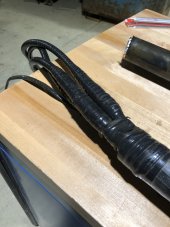
Cables are not terminated with stress comes even though the fuses would indicate it’s higher than 5 kv ) and it is 6.9 kv system but that not written anywhere.

I don’t expect anyone without a very specific skill set to see these things I was just just being a hourses ass and trolling to be honest

To answer your quest about neutrals you do not fuse them
 
It's been a few years since I last made up stress cones. But, it was a big time saver when they came out with the cold shrink kits.
Making high voltage terminations , is a dieing skill set.
I don't miss it at all, but it was very good money.
 
  • Like
Reactions: DPC
It's been a few years since I last made up stress cones. But, it was a big time saver when they came out with the cold shrink kits.
Making high voltage terminations , is a dieing skill set.
I don't miss it at all, but it was very good money.
All the young guys use the 3m cold shrink kits
Funny thing happens a couple months ago they got a pour kit.
It’s still uses the same sleeves but you had to pour the final mechanical protection( you know like an old time 3m old underground pour splice for a regular armoured cable

They couldn’t d the job

Another time we were caught with no kits but I found some new old stock raychem hot shrinks
That’s was good kit but again the young guys could not use it.

And of course there is still semi tape and rubber tape
I’ve show a few Guys how to tape
Explained how stress control works with a deflector if you dont have any high k tape….
But that’s out of fashion now and everyone is scared it may not work with predictable results like a pre manufactured 3m cold shrink

Now your results are very dubious
Young guys don’t know what they are doing
Can’t tape anything….

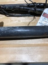
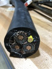
This is shielded 8 kv ggc
It look like regular portable power cable
Young guys have no idea what’s out there because they were never trained right
I worry they will make a mistake and cut a live one of these because they don’t understand what was done and how it was done in the past

E1CDDAA7-4D07-4913-9421-95FE2A404BA8.jpeg
 

Attachments

  • B909E86F-019C-43F4-B6A9-4238502BA8E8.jpeg
    B909E86F-019C-43F4-B6A9-4238502BA8E8.jpeg
    178.1 KB · Views: 1
  • 65C9E4EB-D8D6-4D4F-8B4A-1FB2000AC9CF.jpeg
    65C9E4EB-D8D6-4D4F-8B4A-1FB2000AC9CF.jpeg
    143.8 KB · Views: 1
When I was coming up. We had one guy who knew how to make the terminations. For some reason he liked me and taught me how. When he died, I became the one guy. It wasn't something that my company done regularly. So they didn't see any reason for a second guy. Luckily for them, my predecessor did.
 
  • Like
Reactions: DPC
So we have a piece of heavy equipment that has a 24V system that uses two 12v Batts in series

The prior owner had wired a stereo to one of the batteries. That thing would eat batteries to the tune of every couple years before I came on board. I was shocked to see how quickly even the small draw the the batteries out of balance.


With that said, we have some military vehicles that tap 12v in between batteries. The oem mnfr doesn't seem to think it's an issue. I dunno.
 
Last edited:
  • Like
Reactions: DPC
So we have a piece of heavy equipment that has a 24V system that uses two 12v Batts in series

The prior owner had wired a stereo to one of the batteries. That thing would eat batteries to the tune of every couple years before I came on board. I was shocked to see how quickly even the small draw three the batteries out of balance.


With that said, we have some military vehicles that tap 12v in between batteries. The oem mnfr doesn't seem to think it's an issue. I dunno.
In an auto motive application you have an alternator that’s constantly changing at 14 or 28 volts
Almost always doing an equalization charge

Not sure about the USA but in the 80s the Canadian army had a lot of chev or gm trucks wired that way
28 volt and 14 volt charging

I see more surviving power power wagons on the road.
Probably a reason for that
Less to go wrong
 
Last edited:
With that said, we have some military vehicles that tap 12v in between batteries.

Hmmm, that does make me think of an interesting possibility - still not a good idea...

If all the charging were done with independent (read electrically isolated except for their connection to the batteries) power sources at 12v - say two separate alternators - to separately charge two 12v batteries which happen to also be in series for some loads. I think that might work longer term from a balance perspective.

Obviously, this still has serious downsides:
  • The conventions/safety problem I highlighted initially
  • Any capacity used at 12v would impact the capacity of the 24v system and each 12v "rail" would have access to only half the total (usable) power in the battery
  • Higher costs due to all the charging equipment needing to be 12v stuff and duplicated

I recall someone made an alternator that tapped off ac before the regulator to provide power for something else

I think it was a truck….
What did they use the ac for?
Dammed if I can recall
Maybe defrosting heating seats????


Anyhow a smart fellow could do this with a modern one, feed that into a solid state rectifier regulator off a tractor or something else that does the job you want
 
Assuming your first sentence is two 12V batteries in SERIES, and the batteries are LiFePO4 with BMS.

I find it best to use 12V charge controllers for each series battery, and 24V inverter for the series pair.

Then it is fine to run 12V loads from individual batteries.

This obviously isn’t an option if you use all-in-one inverter/chargers.
Hmm, Never thought of that. Could I still pull 24 V for inverter loads?
A
 
That's an interesting way to go about it. But I would be concerned that the SCC's wouldn't evenly charge. But I guess that it would just limit the capacity of the whole bank. As long as it wasn't the same one always being the low one. The lifespan may even out.
 
Back
Top