


You are using an out of date browser. It may not display this or other websites correctly.
You should upgrade or use an alternative browser.
You should upgrade or use an alternative browser.
Active balancer, make it smart!?
- Thread starter Vi s
- Start date
The voltage regulator is only for running the ADUM1201, which uses a few milliamps of current. It would be powered through the UART port on the BMS which seems to have a variable output voltage between 10v and 14v. This obviously won't ever be higher than the voltage of your actual battery itself.
The AMS1117 is usually capable of accepting at least 15v input, though any 3.3v linear voltage regulator with a maximum input voltage of over 14v will be suitable.
The buck converters you have would also be fine, however definitely overkill for this purpose. If you already have them though, there's no harm in using one.
Many thanks for the detailed clarification, then I will just use one of my hw-618 which can be set via a solder bridge to 3.3v.The voltage regulator is only for running the ADUM1201, which uses a few milliamps of current. It would be powered through the UART port on the BMS which seems to have a variable output voltage between 10v and 14v. This obviously won't ever be higher than the voltage of your actual battery itself.
The AMS1117 is usually capable of accepting at least 15v input, though any 3.3v linear voltage regulator with a maximum input voltage of over 14v will be suitable.
The buck converters you have would also be fine, however definitely overkill for this purpose. If you already have them though, there's no harm in using one.

I've had a chance to expand my test battery and sort out the BMS issues that were slowing progress. Testing is nearly complete with most functions working as expected, most importantly the external relay for the active balancer.
The shared UART connection still needs a bit of work, which will allow both the STM32 and the bluetooth adaptor to communicate with the BMS at the same time. Once that's working I'll post the code and start documenting how it all fits together.

The shared UART connection still needs a bit of work, which will allow both the STM32 and the bluetooth adaptor to communicate with the BMS at the same time. Once that's working I'll post the code and start documenting how it all fits together.
Looks great and makes me want to order the display as well... Is yours the touch version or the normal one? The 2.4inch or 2.8inch since both are 240x320?I've had a chance to expand my test battery and sort out the BMS issues that were slowing progress. Testing is nearly complete with most functions working as expected, most importantly the external relay for the active balancer.
The shared UART connection still needs a bit of work, which will allow both the STM32 and the bluetooth adaptor to communicate with the BMS at the same time. Once that's working I'll post the code and start documenting how it all fits together.
View attachment 138778
How much power does this whole setup consume? Is that screen power hungry?
Just saw the screen for half the price as compared to last time i checked... i guess this must be a sign...
Last edited:
I'm using the 2.4" non-touch version.Looks great and makes me want to order the display as well... Is yours the touch version or the normal one? The 2.4inch or 2.8inch since both are 240x320?
How much power does this whole setup consume? Is that screen power hungry?
Just saw the screen for half the price as compared to last time i checked... i guess this must be a sign...
The STM32, the TFT display and the ADUM1201 combined consume 51mA or 0.26W while running.
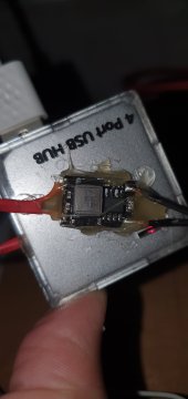
If you're going to buy the TFT display, make sure it's the 3.3v version. I've attached a photo of the back of mine to help you identify a similar model.

Other than this, the final tests are done with the bluetooth and STM32 now able to communicate with the BMS at the same time. There's a couple minor modifications I want to make to the display so it shows the external balancer status and the highest/lowest cell numbers before I post the code.

Many many thanks, absolute amazing work!
Convinced, will order the screen as well, would be a shame if i wouldn't.
Is there a way to put the screen to sleep like when no current is flowing? ..to save power but more importantly from screen burn-in. But since it's not an ips panel i shouldn't be so likely. Maybe an on-off button/switch... Does your screen run all the time?
I leave my screen on 24/7, never seen any evidence of burn-in. One of the wires (connected to the TFT display LED pin) controls the backlight, you could easily put a switch inline with it if you wanted to save a bit of power, but it won't change what's being displayed, you just won't be able to see it.Is there a way to put the screen to sleep like when no current is flowing? ..to save power but more importantly from screen burn-in. But since it's not an ips panel i shouldn't be so likely. Maybe an on-off button/switch... Does your screen run all the time?
augiedoggy
New Member
- Joined
- Oct 26, 2022
- Messages
- 142
just curious if it is possible to integrate with the existing uart or rs485 protocal touchscreens they already make for these bms units like the one I have in my golf cart already? https://www.aliexpress.us/item/3256...2ES75mV&gatewayAdapt=glo2usa&_randl_shipto=US Or would that result in even more work?
Last edited:
I don't have one of these to analyse or experiment with, so I could only guess.just curious if it is possible to integrate with the existing uart or rs485 protocal touchscreens they already make for these bms units like the one I have in my golf cart already? https://www.aliexpress.us/item/3256...2ES75mV&gatewayAdapt=glo2usa&_randl_shipto=US Or would that result in even more work?
I think the RS485 version would be fine, as it connects to a different port on your BMS (if available), so it shouldn't interfere with anything else.
If your BMS doesn't have RS485 available, I suspect the UART version of the screen could work if plugged into the STM32 in place of the bluetooth module.
That's good to hear, thanks again!I leave my screen on 24/7, never seen any evidence of burn-in. One of the wires (connected to the TFT display LED pin) controls the backlight, you could easily put a switch inline with it if you wanted to save a bit of power, but it won't change what's being displayed, you just won't be able to see it.
OK, I'm pretty sure it's all done, the code and basic instructions have been posted here: https://github.com/octal-ip/STM32_JBD_BMS_Monitor
?OK, I'm pretty sure it's all done, the code and basic instructions have been posted here: https://github.com/octal-ip/STM32_JBD_BMS_Monitor
Just ordered the last part, the screen. Now the waiting game starts.
I read the basic instructions but couldn't get a complete picture of how to assemble it. Would it maybe be possible to add a simple sketch? Something like following


That would help immensely! A sketch by hand would be already enough.
?
Just ordered the last part, the screen. Now the waiting game starts.
I read the basic instructions but couldn't get a complete picture of how to assemble it. Would it maybe be possible to add a simple sketch? Something like following
That would help immensely! A sketch by hand would be already enough.
I've uploaded the wiring layout to GitHub and attached it to this post. You'll see why I tabulated all the connections in the documentation - it's a bit of a rats nest to look at.
For these kinds of projects I prefer to mount all the modules to "dotted veroboard" using female pin headers. This way the point-to-point wiring can be soldered on the underside while still producing a reliable and clean end product with removable modules.
A word to the wise: using jumper or "DuPont" wires is fine for prototyping, but they're far too unreliable for permanent applications. Be prepared to spend a bit of time with the soldering iron and wire cutters.

Thank you so much, very clear and nice diagram! Yes in conjunction with the table it's an A+ documentation!I've uploaded the wiring layout to GitHub and attached it to this post. You'll see why I tabulated all the connections in the documentation - it's a bit of a rats nest to look at.
For these kinds of projects I prefer to mount all the modules to "dotted veroboard" using female pin headers. This way the point-to-point wiring can be soldered on the underside while still producing a reliable and clean end product with removable modules.
A word to the wise: using jumper or "DuPont" wires is fine for prototyping, but they're far too unreliable for permanent applications. Be prepared to spend a bit of time with the soldering iron and wire cutters.
Excellent tips! Me too, was planning to do the same, still have a few veroboards left. Good idea with the female pin headers, will check if i have enough of them left as well.
I put my full trust in you so i am going to skip the Dupont prototyping step.
augiedoggy
New Member
- Joined
- Oct 26, 2022
- Messages
- 142
Well it seems this thread has gone more in the direction of a uart based solution but for reference I was able to get this to work.. I removed the relay and soldered it remotley with wires to open and close the contacts at the desired voltageI have a 16s 48v golf cart pack that I currently has a rocker switch soldered to the run wires on my heltec style active balancer... if I am understanding this correctly I can just wire this voltage controlled switch up to have the balancer kick on when the pack reaches say 54v right?

CD60L Solar Battery Charger Controller 12V 24V 48V Charging Discharge Control | eBay
It can be used for DC 6V~60V any one lithium/lead-acid battery. Display symbol OUT indicates discharging mode. Display symbol IN indicates charging mode. Support charging protection. Dual mode work.www.ebay.com
Evngb
New Member
Could you please share some more details, esp. the software code and the hardware that you used. Thanks in advance!I've taken a bit of a different approach to this issue and addressed most of it in software. I have a JK BMS, and have been using the amazing esphome-jk-bms software by syssi to monitor and send all the BMS statistics to MQTT. With a small modification, I've configured this to switch a relay on once any cell voltage is above 3.4v, then off again as the highest cell drops below 3.35v (to provide some hysteresis). The relay is connected across the "run" pads on a 5A Hankzor active balancer. This minor modification cost me $2 and provides the ideal "smart" balancer to compliment the JK BMS.
Why do this when the JK BMS already has an active balancer?
I had the Hankzor balancer sitting on a shelf from a previous project, so no point having it just collect dust.
The Hankzor also uses a different cascading balancing method to the JK BMS, which just drains and charges the highest/lowest cells, so the two compliment each other quite well.
Happy to share my ESPHome YAML file for any JK BMS owners who might find it useful.
All the details are here in the thread, including links to my GitHub repository.Could you please share some more details, esp. the software code and the hardware that you used. Thanks in advance!
Edit: sorry, I realised you were talking about the original ESPhome/JK BMS variant. I've uploaded it all to GitHub here: https://github.com/octal-ip/ESP32_JK_BMS_Monitor
Last edited:
Glad to hear, if you like to share more details of your modification please feel welcome!Well it seems this thread has gone more in the direction of a uart based solution but for reference I was able to get this to work.. I removed the relay and soldered it remotley with wires to open and close the contacts at the desired voltage
For different needs and circumstances, different solutions are required. So the bigger the collection of solutions to choose from the better, isn't it!?
augiedoggy
New Member
- Joined
- Oct 26, 2022
- Messages
- 142
Oh I am not complaining... I asked the question about the module I was looking to purchase and got no response as the conversation had drifted in another direction which is why I mentioned it in my followup.Glad to hear, if you like to share more details of your modification please feel welcome!
For different needs and circumstances, different solutions are required. So the bigger the collection of solutions to choose from the better, isn't it!?
Similar threads
- Replies
- 4
- Views
- 377
- Replies
- 13
- Views
- 721
- Replies
- 6
- Views
- 381
- Replies
- 1
- Views
- 233
- Replies
- 4
- Views
- 564