Thanks for your response mate!
1. 2AWG should be used for the 100A connections between the battery and the Distribution Fuse Block. 12AWG wire should be used for the 15A connection between the charge controller and the battery
I've looked at a bunch of different DC Max Amperage charts that range from 4AWG to 1AWG - I'll err on the side of caution and use 2AWG as you suggest. What resources do you refer to when calculating these things? I was surprised to see such variety in the charts I was looking at.
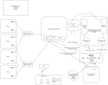
2. The shunt can only measure current that passes through it. Typically the charge controller is connected to the load side of the shunt. In this configuration the shunt can measure both charge and discharge current in and out of the battery thus keeping an accurate SoC. However, when the solar panels are producing, any current that goes directly to the loads will not be measured by the shunt.
In the attached diagram the MPPT negative battery connection is attached to the load side of the shunt. I'll keep it this way. Are you suggesting I would need multiple shunts in order to accurately measure both discharge and PV charge? I would get the most utility out of measuring discharge, but if I want to see the PV charge I guess I can turn off all the loads during the day and have a look, then switch them back on. Have I got this right? Sorry I'm a little confused.
3. Couple of issues: The charge controller is rated for 100V maximum and the panels have a Voc of 45.4V x 2 = 90.8V. Datasheet Voc values are measured at STC which is 25 deg. C. At 0 deg. C the Voc will increase by about 7 volts. What is the coldest outdoor temps you expect.
The charge controller is rated at 220W max for a 12V system, any extra power will be wasted. You really only need 2 panels connected in parallel to the charge controller. To fully utilize all 4 panels you need 2 charge controllers which will provide up to 30A of charging. As long as the battery is at least 100Ah then your charge rate will be acceptable at 0.3C.
I agree 90.8V is quite close for my liking. The location is outback Australia. The coldest outdoor temperature on record is -0.3° but it never really gets that low during the day. The panels are second hand, would that mean the output will probably be lower than new? I understand the way forward right now you're suggesting is just to use two panels in parallel, but I will be using more of the same panels in series in the future so would like to know if I can get away with 90.8V on a 100V MPPT
Where do you get the MPPT 220W max from? Is this the "Nominal PV power, 12V 1a,b)" in the manual? Do you know how this is calculated?
The batteries are 100AH and will charge at up to 0.5C comfortably. Although I understand the 100/15 MPPT I'm using right now will only put out 15A not 50A
I have 8 of these panels total so my guess is in the future I'll be running a Victron 100/30 or 100/50 MPPT and using all 8 panels with a 2S4P set up and running a 24V or 48V system.
3. I believe the battery protect will monitor both amperage and voltage and will disconnect either on high current or low voltage (which roughly correlates to SoC) so the battery doesn't get too low. Do you really need this functionality if the shunt is monitoring SoC? If not then a fuse would be a much easier solution as you noted on the drawing.
As to your question specifically: The Batt Protect device is uni-directional and would be inserted into the Positive cable shown on your diagram connecting Battery Pos+ to the M5 ring terminal on the Distribution Fuse Block. Follow the Victorn wiring diagram as current will only flow one direction when the device is in the ON state.
My impression of the Victron Smart BatteryProtect 100A is that it shuts off any loads from the battery to protect the battery from damage occurring due to discharging the battery too much. I was only aware of it sensing voltage which as you say, is a rough corollary for SoC.
The shunt is monitoring and pushing to a gauge. The need for a BatteryProtect would be realised if somebody left the lights on and forgot about it, thus discharging the battery. I don't see how a fuse could provide the same functionality?
The 100A fuse I thought about putting between the + battery and positive ring terminal on the distribution board was only the prevent the cumulative fused loads of 30A getting any higher than 100A. The board has about 12 outputs each rated up to 30A but the whole unit can't go over 100A.
Thanks so much, I really appreciate all your help
How's the weather in California?


") Well insulated houses in Australia are virtually non-existent.
Well insulated houses in Australia are virtually non-existent.